background image

     www.amico.com    21

Section 4: Adjustments

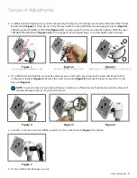
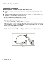
2.  A sufficient level of tightness may not be achieved by the time the Tilt-setting Lever touches the back of the Patient 

Monitor Shelf 

(Figure 1)

. If this occurs, PULL the lever AWAY from the MON Head to disengage the lever 

(Figure 2)

TURN the lever COUNTER-CLOCKWISE 

(Figure 3 [1])

 to create space for the lever to further tighten. PUSH the lever 

TOWARDS the MON Head 

(Figure 3 [2])

 to re-engage the lever. Repeat Step 1 to further tighten the Tilt Hinge.

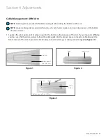
3.  If a sufficient level of tightness cannot be achieved, use a 4 mm Allen key to loosen the screw that keeps the Tilt-

setting Lever in place 

(Figure 4)

. Remove the screw and spring 

(Figure 5)

. Remove the lever to reveal the 12 mm 

hex-nut 

(Figure 6)


NOTE:

 In some instances (especially with heavy monitors), a sufficient level of tightness cannot be achieved. If 

monitor tilt-angle will not set, proceed to Step 3.

4.  Turn the 12 mm hex-nut CLOCKWISE using the 12 mm socket wrench 

(Figure 7)

 to tighten.

5.  Test to confirm the tilt-angle is secure.

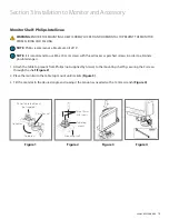
Figure 4

Figure 6

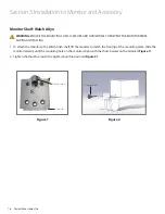
Figure 7

Figure 5

Spring

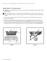
Figure 1

Lever blocked by Patient Monitor Shelf

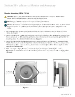
Figure 2

Pull lever AWAY from the MON Head

Figure 3

Rotate Lever COUNTER-CLOCKWISE [1] and PUSH [2]

1

2

Summary of Contents for AHM

Page 1: ...Installation Instructions Manual Adjustable Height Monitor AHM Arm...

Page 2: ...indirect result of failure to comply with the instructions provided in this manual Please note these key words and symbols WARNING Steps where extra care should be taken to prevent injuries and damag...

Page 3: ...itor Shelf 3 76 2 mm Top Back Mount 5 127 mm Top Back Mount and VESA 13 Monitor Shelf 6 152 4 mm Drop On 14 Monitor Shelf Philips Intellivue 15 Monitor Shelf Welch Allyn 16 Monitor Mounting VESA 75 10...

Page 4: ...ay hardware nor the tools necessary for assembly All above in grey text A B 1 2 3 4 Item Item number Quantity Phillips screw driver 2 A1 1 Hex keys 1 8 0 3 cm 3 16 0 5 cm M3 M4 A2 1 each Socket wrench...

Page 5: ...FASTENERS AND THE PROPER INSTALLATION OF EQUIPMENT REGARDLESS OF WHAT IS SUPPLIED WITH YOUR AHM MONITOR ARM SEE RAIL INSTRUCTIONS FOR SPECIFIC WALL CHANNEL GUIDELINE INFORMATION WARNING VERIFY THE WEI...

Page 6: ...Mounting Adapter VESA LCD mount shown other options available 2 Monitor Head Rotation Monitor rotation adjustment 3 Height Locking Lever Locks the arm at a desired height 4 Counter Balance Used to ad...

Page 7: ...in the highest vertical position support the bottom of the arm and guide the MON channel adapter into the top of the wall channel 2 Once the arm is at the desired height tighten all four screws on th...

Page 8: ...M arm locked in the highest vertical position support the bottom of the arm and guide the head of the top screw into the opening of the rail Figure 1 Ensure the flange on the GTA is properly aligned w...

Page 9: ...Figure 3 and 6 NOTE On the side of the V adapter and the D adapter there are screw knobs that lock the adapter into the rail once secured When you turn the knob counter clockwise the side of the adapt...

Page 10: ...ten once inserted Figures 4 and 5 3 Tighten screw knobs with a 3 16 4 76 mm HEX key when adapter is at desired height Once tightened the screw knob will protrude from the other side Fasten the nut to...

Page 11: ...er lip into the inside lip of the ARS rail hold the tab on the ARS and push the ARS adapter into the rail Once secure release the tab Figure 1 2 Mount the AHM arm by angling the top ARS adapter attach...

Page 12: ...SURE THE MONITOR SHELVES PLATES PROVIDED BY AMICO ACCESSORIES INC OR OTHER MANUFACTURERS ARE ASSEMBLED AS DIRECTED AND MATCH THE SHELF REQUIREMENT IF A MONITOR SHELF OR PLATE DOES NOT MATCH THE REQUIR...

Page 13: ...it 1 First install the mounting adapter to the device Please refer to the adapter installation manual provided with the adapter Figure 1 2 Loosen the plastic screws on the bottom side of the mounting...

Page 14: ...Please refer to the adapter installation manual provided with the adapter 2 Lift the monitor and slide the mounting adapter plate on to the mounting shelf Slide the monitor down until the mounting ho...

Page 15: ...ngers 1 Attach the table top mount from Philips not supplied by Amico to the mounting shelf by securing the 3 screws through the shelf Figure 2 2 Place the monitor to the table top mount until it clic...

Page 16: ...tor to the Welch Allyn shelf lift the monitor to match the front lip of the mounting plate Slide the monitor laterally until the mounting hole on the monitor aligns with the thumb screw on the adapter...

Page 17: ...p 2 holes in the back of the display The display can then be hung up on the VESA Head through the two slots at the top Insert 2 more screws through the VESA 100 mounting holes at the bottom and tighte...

Page 18: ...different accessories that attach to the head of the AHM Arm Figure 1 Figure 5 Figure 2 Figure 6 Figure 3 Figure 7 Figure 4 Figure 8 6 and 12 post 152 4 mm and 304 8 mm Single or dual cord holder Key...

Page 19: ...nd of Extension Applies to AHM IT Stations with Extension Arm AHM 55 15 35 75 and AHM IT 55 15 35 75 To rotate at the end point near wall push on the side of the extension arm near the mid way point F...

Page 20: ...O SECURE THE MONITOR IN PLACE PROCEED TO STEP 3 WARNING DO NOT ADJUST TILT ANGLE WITHOUT FIRST LOOSENING THE TILT SETTING LEVER NOTE Tilt angle setting is ONLY ACHIEVED BY TIGHTENING THE TILT SETTING...

Page 21: ...evel of tightness cannot be achieved use a 4 mm Allen key to loosen the screw that keeps the Tilt setting Lever in place Figure 4 Remove the screw and spring Figure 5 Remove the lever to reveal the 12...

Page 22: ...an 135 Figure 2 2 To adjust the tension of the portrait and landscape feature for VESA 75 plate The monitor must be removed from the Monitor Head Remove the four VESA 75 screws from the monitor Turn t...

Page 23: ...nd 3 Section 4 Adjustments Figure 1 Figure 2 Figure 3 Rotational Tension Bolt VESA Rotation Stopper Built in Stopper VESA Rotation Stopper Built in Stopper Height Locking Lever Adjustments WARNING THE...

Page 24: ...n the following order from the top down 1 2 12 7 mm bolt bronze washer bracket arm metal washer in upper washer groove AHM arm between the bracket metal washer in lower washer groove bracket arm bronz...

Page 25: ...nce the monitor is securely installed release the height lock and position the AHM arm to align the opening in the cover with the counter balance bolt Tighten the locking lever again to lock the AHM a...

Page 26: ...n the AHM arm to align the opening in the cover to the counter balance bolt Tighten the locking lever again to lock the AHM arm 3 To adjust for no load tighten the counter balance bolt counter clockwi...

Page 27: ...arms 1 Squeeze the cable guide until its edges snap into the bottom surface grooves of the arm If you encounter difficulty you may use a flathead screwdriver to force the cable guide into the groove L...

Page 28: ...PERIODIC INSPECTION AND MAINTENANCE TO PERFORM OPTIMAL AND TO ACHIEVE ITS MAXIMUM OPERATION LIFE WARNING THE FOLLOWING SCHEDULE IS A RECOMMENDATION AND NOT A STRICT SCHEDULE MAINTENANCE SCHEDULES SHO...

Page 29: ...e bolt is tightened to the tightest position C Check for any signs of gapping between the bushing and the head Also ensure the head of the AHM is horizontal and is secure D Inspect the bolt washers an...

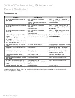
Page 30: ...alance is not balanced properly Height locking lever is not tighten properly Please see counterbalance section of the manual See page 25 The AHM arm is not secure and is rocking slightly Loosened dama...

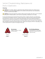
Page 31: ...ach ammonia or alcohol solutions The surface finish will be permanently damaged by strong chemicals and solvents such as acetone and trichloroethylene Steel wool or other abrasive material should neve...

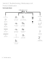
Page 32: ...ension Arm 0 5 12 7 cm Shelf with 30 tilt limit 3 Philips IntelliVue with 30 tilt limit 6 5 12 7 cm Shelf for back mounts 8 3 7 6 cm Shelf with 30 tilt limit 9 3 76 2 mm Shelf for back mounts W Welch...

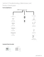
Page 33: ...ooting Maintenance and Product Classification B Black Color W White 55 16 40 6 cm Extension Arm 15 12 30 5 cm Extension Arm 05 No Extension Arm 35 9 22 9 cm Extension Arm 75 6 15 2 cm Extension Arm MO...

Page 34: ...irst be approved by Amico Accessories Inc A valid Return Goods Authorization RGA number must be obtained from Amico Accessories Inc prior to commencement of any service work Warranty work which has no...

Page 35: ......

Page 36: ...USTABLE HEIGHT PATIENT MONITOR ARM MANUAL 05 17 2021 Amico Accessories Inc 85 Fulton Way Richmond Hill ON L4B 2N4 Canada Toll Free Tel 1 877 264 2697 Tel 905 763 7778 Fax 905 763 8587 Email info amico...

Reviews: