amiad DVF Installation, Operation And Maintenance Instructions Download Page 15


910101-001048 

                                         12/2019 

Page 15 of 42 


Media Filling Process  


Before filling the vessel, please follow these steps: 


Visually inspect the inside of the vessel to ensure all 

the media retaining nozzles are present and fixed in 

place.  


When performing this inspection:  

o


Ensure that you are wearing the correct PPE. 

o


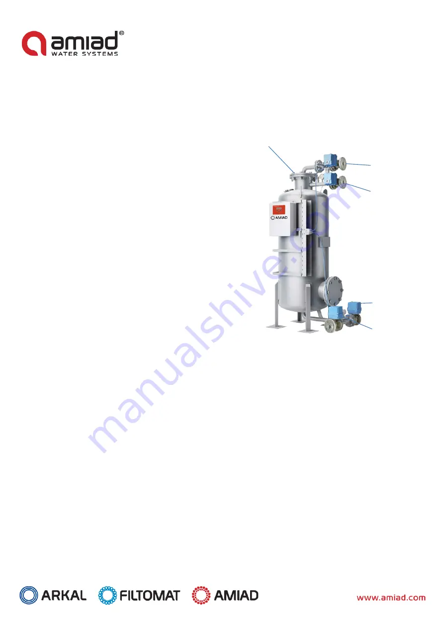
Locate the top flange – see fig. A.       

o


Now  carefully remove the bolts on the top flange. 

This will  release the blind flange  and  gasket.  Care 

should be taken not to  damage  the flange, flange 

gasket, or drop the bolts inside the vessel.  

o


Carefully remove the flange and internal pipe-work, 

which has the Dual Vortex Generator attached. This 

will expose the nozzles for inspection. Make sure all 

nozzles are in place. 

o


If any nozzles are missing,  please contact Amiad 

Water Systems before proceeding further. 


DO NOT FILL THE VESSEL IF NOZZLES ARE MISSING.


Make  sure vessel interior is free from any debris 

before following the media filling procedure below.  


It is strongly recommended to use correct PPE during 

media installation. (See media data sheets which can 

be found on the bags, and further in this document). 

o


First  ensure  that  the  valves on the backwash inlet 

V3 and process outlet V2 are closed. 

o


Now, via the top flange, fill half the vessel with clean, fresh water. This is to ensure no damage occurs to the 

backwash nozzles located within the vessel base. 

o


Load the base media in the correct order (beginning with the largest size first – i.e. Grade 3) with the applicable 

quantities, as shown in the Media Data table below. The depth guide is in mm and given as a guideline only. 

o


Level each layer before moving on to the next layer. 

o


Once  the loading is  complete,  the media should  be  within  approximately  20mm of the base of the vortex 

generator. Check this with the length of the vortex inlet pipe as you are filling the vessel to avoid overfilling. 

o


Place the top flange  with the gasket  back onto the vessel in the same orientation as it was removed, 

remembering to securely screw the feed pipe via union. 


The media bags are marked for the grade size. 
 

Fig. A. 

Top 

Flange 

V1

 Process Inlet 

Valve 


V4

 Backwash 

Outlet Valve 


V3

 Backwash 

Inlet Valve 


V2

 Process 

Outlet Valve 


Summary of Contents for DVF

Page 1: ...iltration System Serial Numbers _____________________ Order number _____________________ Catalog number _____________________ Filtration degree _____________________ Year _____________________ Installation Operation and Maintenance Instructions December 2019 Original Instructions 910101 001048 ...

Page 2: ...its content The confidential nature of and or privilege in the file enclosed is not waived or lost as a result of a mistake or error in this file If you received this file in error please notify Amiad immediately at info amiad com This document does not replace any certified drawing procedure or information provided by Amiad in reference to a specific customer site or project Amiad assumes that al...

Page 3: ...First Operation 17 3 Periodic Iinspection 17 4 Monthly Maintenance 17 5 Yearly Maintenance 18 6 Replacing the filter media 18 Parts Maintenance 19 1 Filter Vessel 19 2 Filter Media PEP ACTIVE Activated Filter Media 19 DVF 300 Filter GA Drawing 21 DVF 300 Filter Parts Drawings 22 DVF 300 Filter Parts List 23 DVF 600 Filter GA Drawing 24 DVF 600 Filter Parts Drawings 25 DVF 600 Filter Parts List 23 ...

Page 4: ...scharging wastewater to drain it is the responsibility of the user to determine the legal discharge route for contaminated water from the filter Electrical connections should be done in accordance with national standards and carried out by competent persons only Amiad filtration products always operate as components in a larger system It is essential for the system designers installers and operato...

Page 5: ...ce with the relevant standards and regulations For shipping lifting and positioning the filter use only approved lifting equipment authorized employees and contractors Pneumatics Ensure that the compressed air supplied to the filter never exceeds the maximum designated pressure for the filter An air pressure reduction valve should be installed on the compressed air supply line upstream of the filt...

Page 6: ... use the filter for purposes other than its original design and operational envelope 4 Maintenance Servicing the filter should be performed by an authorized manufacturer s technician only Before any maintenance or non regular operation carefully read the following Disconnect the filter from the power supply and lock the main power switch Disconnect any compressed air supply release the residual pr...

Page 7: ...h water pressure or steam should be performed in accordance with cleaning system instructions local standards and regulations and without endangering the operator or the vicinity Before returning to regular operation Re assemble any protective covers or protection mechanisms removed during service or maintenance operations Ensure that all the tools ladders lifting devices etc used during the maint...

Page 8: ...N10 Flanged Process Water Outlet Connection 1 DN 25 ISOPN10 Flanged 1 DN 40 ISOPN10 Flanged 2 DN 50 ISOPN10 Flanged 3 DN 80 ISOPN10 Flanged Backwash Inlet Connection 1 DN 25 ISOPN10 Flanged 1 DN 40 ISOPN10 Flanged 2 DN 50 ISOPN10 Flanged 3 DN 80 ISOPN10 Flanged Backwash Outlet Connection 1 DN 25 ISOPN10 Flanged 1 DN 40 ISOPN10 Flanged 2 DN 50 ISOPN10 Flanged 3 DN 80 ISOPN10 Flanged Minimum Operati...

Page 9: ...s supplied with multi level graded glass The backwash period is adjustable depending on the nature of the contamination being removed Filter Configuration The DVFis a patented filter system for water which can remove particulate down to 1 micron nominal in size Each unit has a total of four valve connections namely Process Inlet Valve V1 This is the filter s inlet connection for the dirty process ...

Page 10: ... continues on line filtration until backwash is initiated This is usually done via a pressure differential switch supplied as part of the control package a timer adjustable through the controller or manually by pressing the backwash button Once backwash is triggered by either of the above V1 and V2 close the filter will no longer be producing any process water until the backwash cycle is complete ...

Page 11: ... the vessel air inlet If the airline is relatively long calculate the dynamic head loss and take it in to account An air valve MUST be installed to handle the blower air flow with the minimal hydraulic resistance ARI D070P model is recommended A vacuum breaker MUST be installed on the drain line Process Description Partial Draining This stage is designed to enable room on the upper part of the ves...

Page 12: ...he filter and run the BW cycle DVF Scouring Design Table DVF Model Scouring Pressure Bar Scouring Velocity m hr Vessel Diameter m Vessel Area m Nominal Operation Flow m h DVF 300 0 5 0 6 70 0 3 0 07 5 DVF 600 0 5 0 6 70 0 6 0 28 20 DVF 900 0 5 0 6 70 0 9 0 64 45 DVF 1200 0 5 0 6 70 1 2 1 13 79 ...

Page 13: ...nt temperatures of below 2 C without heat tracing If there is any risk of this you should consult with Amiad Water Systems Connect inlet outlet process pipe work backwash and drain to the unit as necessary and check all filter connections for tightness as fittings may become loose during transit Remember not to overtighten the connections If the control panel doesn t come pre mounted mount it adja...

Page 14: ... to the differential pressure switch Electrical Connections Electric wiring must be performed by an authorized electrician only using standardized and approved components Install a lockable main power cut off switch close to the control panel If due to site constraints the control panel is installed without a clear line of vision to the filter an additional lockable power disconnect cut off switch...

Page 15: ... use correct PPE during media installation See media data sheets which can be found on the bags and further in this document o First ensure that the valves on the backwash inlet V3 and process outlet V2 are closed o Now via the top flange fill half the vessel with clean fresh water This is to ensure no damage occurs to the backwash nozzles located within the vessel base o Load the base media in th...

Page 16: ...e 1 Depth mm 181 212 251 212 Weight kg 16 75 200 300 of Bags 3 Bags 8 Bags 12 Bags Grade 2 Depth mm 219 200 287 305 Weight kg 19 75 225 425 of Bags 3 Bags 9 Bags 17 Bags Grade 3 Depth mm 232 218 161 210 Weight kg 20 75 125 290 of Bags 3 Bags 5 Bags 12 Bags Total Bed Weight kg 85 350 800 1465 Total Bed Height mm 951 978 996 1025 Media configurations can vary according to process ...

Page 17: ...Flush the filter until the backwash outlet V4 water is clean Note Ensure minimal backwash flowrate according to the technical data table pp 8 3 Switch to Auto operation mode 4 Adjust all operational setpoints in the control system as per control philosophy Recommendations clean DP 0 3 bar Backwash trigger DP 0 8 bar 3 Periodic Inspection 1 Check for leaks from connections and fittings If leaks are...

Page 18: ...lter media through the service hole on the side of the filter Thoroughly clean the inside of the filter with clean water Inspect the filter mushrooms and the double bottom Carefully close the service covers on the side Fill the filter media through the filling hole top lid and continue to follow the instructions in the section Media Filling Process 6 Replacing the filter media 1 Replace the filter...

Page 19: ...spect condition of securing bolts replace as required 2 Filter Media PEP ACTIVE Activated Filter Media Weekly Maintenance Check and log differential pressure Monthly Maintenance Perform a manual backwash cycle and visually inspect drain for media carry Yearly Maintenance Removal of upper hatches for media inspection Perform a media sanitation disinfection if required solution of hypochlorite 5 Top...

Page 20: ...910101 001048 12 2019 Page 20 of 42 DVF Filter P ID Drawing ...

Page 21: ...910101 001048 12 2019 Page 21 of 42 DVF 300 Filter GA Drawing ...

Page 22: ...910101 001048 12 2019 Page 22 of 42 DVF 300 Filter Parts Drawing ...

Page 23: ...WITCH W BRACKET BACCARA 1 8 BSPM REAR 14BAR 0 5BAR IP66 12794121 1 Various 6 770103 000471 GASKET 1 ISO PN10 EPDM DN25 TH2MM FULL FACE 4 EPDM 7 730104 000573 2 WAY BALL VALVE 1 ISO10 2528 S ST ELECTRIC HQ 004 DN25 GENEBRE ACT SOL 4 Various 7 730104 000573 2 WAY BALL VALVE 1 ISO10 2528 S ST ELECTRIC HQ 004 DN25 GENEBRE ACT SOL 4 Various 7 1 730104 000572 2 WAY BALL VALVE 1 ISO10 2528 S ST W O ACTUA...

Page 24: ...910101 001048 12 2019 Page 24 of 42 DVF 600 Filter GA Drawing ...

Page 25: ...910101 001048 12 2019 Page 25 of 42 DVF 600 Filter Parts Drawing ...

Page 26: ... 316 5 720101 000776 FLUSHING CONTROLLER TECNOLOGIC 5REL S240VAC AC 5 BESPOKE FOR DVF 1 Various 6 720104 000025 DP SWITCH W BRACKET BACCARA 1 8 BSPM REAR 14BAR 0 5BAR IP66 12794121 1 Various 7 730104 000574 2 WAY BALL VALVE 1 1 2 ISO10 2528 S ST ELECTRIC HQ 004 DN40 GENEBRE ACT SOL 4 VARIOUS 7 1 730104 000575 2 WAY BALL VALVE 1 1 2 ISO10 2528 S ST W O ACTUATOR DN40 GENEBRE 4 S ST 304 7 2 720701 00...

Page 27: ...910101 001048 12 2019 Page 27 of 42 DVF 900 Filter GA Drawing ...

Page 28: ...910101 001048 12 2019 Page 28 of 42 DVF 900 Filter Parts Drawing ...

Page 29: ...T316 1 4 BSP BOTTOM 2 W GLYCERINE 2 S ST 316 6 720101 000776 FLUSHING CONTROLLER TECNOLOGIC 5REL S240VAC AC 5 BESPOKE FOR DVF 1 Various 7 720104 000025 DP SWITCH W BRACKET BACCARA 1 8 BSPM REAR 14BAR 0 5BAR IP66 12794121 1 Various 8 730104 000577 2 WAY BALL VALVE 2 ISO10 2528 S ST ELECTRIC HQ 004 DN50 GENEBRE ACT SOL 4 VARIOUS 8 1 730104 000576 2 WAY BALL VALVE 2 ISO10 2528 S ST W O ACTUATOR DN50 ...

Page 30: ...910101 001048 12 2019 Page 30 of 42 DVF 1200 Filter GA Drawing ...

Page 31: ...910101 001048 12 2019 Page 31 of 42 DVF 1200 Filter Parts Drawing ...

Page 32: ...ST316 1 4 BSP BOTTOM 2 W GLYCERINE 2 S ST 316 6 720101 000776 FLUSHING CONTROLLER TECNOLOGIC 5REL S240VAC AC 5 BESPOKE FOR DVF 1 Various 7 720104 000025 DP SWITCH W BRACKET BACCARA 1 8 BSPM REAR 14BAR 0 5BAR IP66 12794121 1 Various 8 730104 000579 2 WAY BALL VALVE 3 ISO10 2528 S ST ELECTRIC HQ 008 DN80 GENEBRE ACT SOL 4 VARIOUS 8 1 730104 000578 2 WAY BALL VALVE 3 ISO10 2528 S ST W O ACTUATOR DN80...

Page 33: ...leshooting Flowchart The majority of faults and problems are associated with the installation rather than the filter system itself Here is a flow chart of the most common faults in order that you may check them before calling our service technicians ...

Page 34: ...ve of Amiad 8 This Warranty will not apply to damaged or defective products resulting from or related to i Fire flood power surges or failures or any other catastrophe and or unforeseen occurrence such as but not limited to those for which the Buyer is customarily insured for or any force majeure events ii Fault abuse or negligence of the Buyer iii Intake water not meeting the agreed standards as ...

Page 35: ...910101 001048 12 2019 Page 35 of 42 Annex A Media Safety Data Sheet 7 pages ...

Page 36: ...910101 001048 12 2019 Page 36 of 42 ...

Page 37: ...910101 001048 12 2019 Page 37 of 42 ...

Page 38: ...910101 001048 12 2019 Page 38 of 42 ...

Page 39: ...910101 001048 12 2019 Page 39 of 42 ...

Page 40: ...910101 001048 12 2019 Page 40 of 42 ...

Page 41: ...910101 001048 12 2019 Page 41 of 42 ...

Page 42: ...r the CE marking in conformity with the art 4 par 3 Pressure Equipment Directive 2014 68 EU Manufacturer Amiad Water Systems Ltd D N Galil Elyon 1 1233500 Israel Tel 972 4 690 9500 Fax 972 4 814 1159 Email info amiad com EC Representative for CE Matters Obelis S A Boulevard Général Wahis 53 B 1030 Brussels BELGIUM Email info obelis com ...

Reviews: