background image


48" AGF                                                  910101-001049 / 01.2020 


Page 12 of 21                  


3.


The Filtration Process 


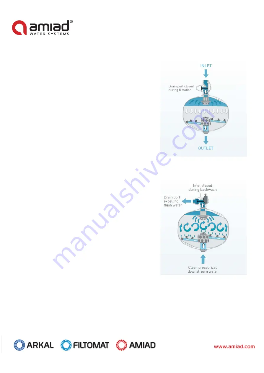
Filtration with media filters, also known as depth filtration, is done by 

filtering water through a thick layer of graded particles, called the filter bed. 

These particles can be sand, gravel or other granular materials. The filtration 

degree depends on the effective size of the bedding and the water velocity 

through the filter. 

Raw water enters from the filter inlet and percolates through the filter bed. 

Suspended materials come into contact and attach to the media particles. 

Filtered water flows through the filtration nozzles and out through the filters 

outlet. 


4.


The Backwash Process 

Cleaning is done by backwashing; pressurized water flows in reverse 

direction – from the nozzles upwards, causing suspension of the filter bed, 

thus releasing the suspended matter from the bedding. The dirt particles are 

then washed out of the filter through the backwash valve. In automatic 

media filters installations, the cleaning process is initiated by the system’s 

controller. When the pressure differential switch senses that the differential 

pressure across the system reached a pre-set value, a signal is sent to the 

backwashing controller and the self-cleaning process begins.  


The restriction control flow valve on the drain manifold needs to be adjusted 

properly. This is essential so debris will be backwashed out of the filter while 

the media will remain in the filter tank. 


Summary of Contents for AGF

Page 1: ...020 Page 1 of 21 AMIAD Water Systems Ltd 48 AGF Automatic Filtration System Serial number Order number Catalog number Tested by Installation Operation and Maintenance Instructions Ref 910101 001049 01 2020 Original Instructions ...

Page 2: ...is document or its Content The confidential nature of and or privilege in the file enclosed is not waived or lost as a result of a mistake or error in this file If you received this file in error please notify Amiad immediately at info amiad com This document does not replace any certified drawing procedure or information provided by Amiad in reference to a specific customer site or project Amiad ...

Page 3: ... 8 DIMENSIONAL DRAWING 10 AGF FILTERS WORKING PRINCIPLE 11 1 MEDIA FILTERS 11 2 HOW THE AGF FILTERS OPERATE 11 3 THE FILTRATION PROCESS 12 4 THE BACKWASH PROCESS 12 INSTALLATION 13 1 PRE INSTALLATION ERROR BOOKMARK NOT DEFINED 2 FILTER ASSEMBLY 13 3 LEAKAGE TEST 14 4 FILLING UP THE MEDIA 14 5 INITIAL OPERATION 14 MAINTENANCE 15 1 GENERAL INSPECTION 15 2 PERIODIC INSPECTION 15 3 ANNUAL INSPECTION 1...

Page 4: ...epending on type of media filtration degree water quality Vessel volume 780 Liters 206 US Gallons Filtration surface area 1 13 m2 12 16 ft2 Filter weight empty filter only 132 kg 291 lbs Media weight 732 Kg 1610 lbs Water weight 370 Kg 814 lbs 2 Backwashing Data Backwash valve 100 mm 4 Backwashing cycle time 2 4 hours 2 4 hours Backwashing time single unit 90 120 seconds 90 120 seconds Backwashing...

Page 5: ...eight 590 kg 1300 lbs Recommended number of media bags approximation Media Composition No of media bags Media bag size kg lbs Gravel 1 28 25 55 Quartz 2 PEP Active 14 14 25 55 Quartz 2 Quartz 0 14 14 25 55 quartz 2 is a support layer of coarse media spread below distribution nozzles dead area 5 Silica Sand Gravel Data Media type Mesh range Average effective size gravel mm inch Crushed Silica 12 80...

Page 6: ...installation instructions provided with the filter by the manufacturer and according to the description given in this manual 2 Make sure to leave enough clearance to enable easy access for future treatments and safe maintenance operations 3 The user should arrange suitable lighting around the area of the filter to enable good visibility and safe maintenance 4 The user should arrange suitable platf...

Page 7: ...he user should install a manual water cut off valve next to the filter s inlet port 3 In cases where the downstream piping network of the filter is pressurized an additional manual water cut off valve should be installed next to the filter outlet port 4 The user should make sure that the system includes a pressure release or a drainage valve to enable release of residual pressure prior to any main...

Page 8: ...filter should be done only by technicians authorized by the manufacturer 2 Disconnect the filter from its power supply and lock the main power switch 3 Disconnect the compressed air supply release the residual pressure and lock the pneumatics main valve 4 Disconnect the filter from its water system by closing and securing the manual inlet valve In cases where the downstream piping network is press...

Page 9: ...system instructions the local standards and regulations and without endangering the operator or the vicinity 11 Manual cleaning of filter element using acid or other chemical agents should be performed in accordance with the relevant material safety instructions the local standards and regulations and without endangering the operator or his vicinity Before returning to regular operation 1 Reassemb...

Page 10: ...48 AGF 910101 001049 01 2020 Page 10 of 21 Dimensional Drawing ...

Page 11: ...nd number of the valves depend on the required flow rate raw water quality and the required filtration degree of the system 2 How the AGF Filters Operate The AGF is a pressurized media filter which operates by trapping the suspended particles in unfiltered water as it flows through a bed of media in a pressurized tank The recommended filter media types are crushed basalt crushed silica quartz sand...

Page 12: ... filters outlet 4 The Backwash Process Cleaning is done by backwashing pressurized water flows in reverse direction from the nozzles upwards causing suspension of the filter bed thus releasing the suspended matter from the bedding The dirt particles are then washed out of the filter through the backwash valve In automatic media filters installations the cleaning process is initiated by the system ...

Page 13: ...y barriers to enable easy access to the filter Do not climb on pipes and other equipment 5 Flush the main water line thoroughly before connecting it to the filter This way any large debris that may damage the filter will be removed 6 Locate the filter in its place and pay close attention to the correct direction of water flow 7 Refer to the below drawing for reference of recommended installation 2...

Page 14: ...nozzles are covered 5 Fill the media through the tank s top access port up to the level indicated on the label affixed to the filter tank exterior 35 cm above distribution nozzles If two media grades are used start with the coarse media and fill it just above the nozzles line 1 pour the finer media to the level indicated on the label affixed to the filter tank exterior 35 cm above distribution noz...

Page 15: ...the media is not washed out Otherwise make sure that the distribution nozzles are not damaged 3 If needed complete the missing amount of media up to the required level as described on page 14 4 Close the service port restart the system and perform several backwash cycles before returning the system to regular operation 4 Replacing the Media 1 The media is replaced depending on a few parameters and...

Page 16: ...sure Hydraulic command system failure Check to be sure the isolationvalve is in the on position Remove one of the hydraulictubes leading to the solenoids and verify that pressurized water is available Inspect the hydrauliccommand filter for contamination Filter station differential pressure remains high after backwash Gauge error Check gauge differential on manifolds against the differential gauge...

Page 17: ...amage replace if cracked or defective Torn or cracked O ring Remove top access cover and inspect vent O ring for damage replace if necessary Damaged vent Inspect vent for possible cracks replace if necessary One or several filters will not backwash Controller output problem Check for correct controller output with multi tester or switch solenoid wires with another station to check for output signa...

Page 18: ...ous 9 18 710101 000394 Outlet R P P 1 19 720601 000044 Grp Body GRP 1 20 760109 000108 Handle S ST 3 21 710103 000383 Lower Cover R P A 1 22 770101 000019 O Ring 76 4 EPDM 2 23 710101 000413 Lower Plug R P A 2 24 700190 000153 Lower Cover Complete Various 1 25 770104 000020 Shaped Seal 45 Shore EPDM 2 26 710103 000380 Bridge R P A 2 27 710101 000404 Tightening Screw R P A 2 28 700190 000158 Bridge...

Page 19: ...48 AGF 910101 001049 01 2020 Page 19 of 21 Parts Drawing ...

Page 20: ...tative of Amiad 8 This Warranty will not apply to damaged or defective products resulting from or related to i Fire flood power surges or failures or any other catastrophe and or unforeseen occurrence such as but not limited to those for which the Buyer is customarily insured for or any force majeure events ii Fault abuse or negligence of the Buyer iii Intake water not meeting the agreed standards...

Page 21: ... bear the CE marking in conformity with the art 4 par 3 Pressure Equipment Directive 2014 68 EU Manufacturer Amiad Water Systems Ltd D N Galil Elyon 1 1233500 Israel Tel 972 4 690 9500 Fax 972 4 814 1159 Email info amiad com EC Representative for CE Matters Obelis S A Boulevard Général Wahis 53 B 1030 Brussels BELGIUM Email info obelis com ...

Reviews: