AMI Ecast View B75B Installation Instructions Manual Download Page 1


Page 1 of 8 


26683851 


REV. A 


 Ecast View B75B Motherboard Upgrade Kit


Kit #26683801 


This kit will not support the Ecast View COIM Board.  If your View core computer 
has the Ecast View COIM board installed you must order the AMI Hardware 
conversion Kit # 26683513. 


Tools Required 

#2 Phillips Head Screwdriver. 


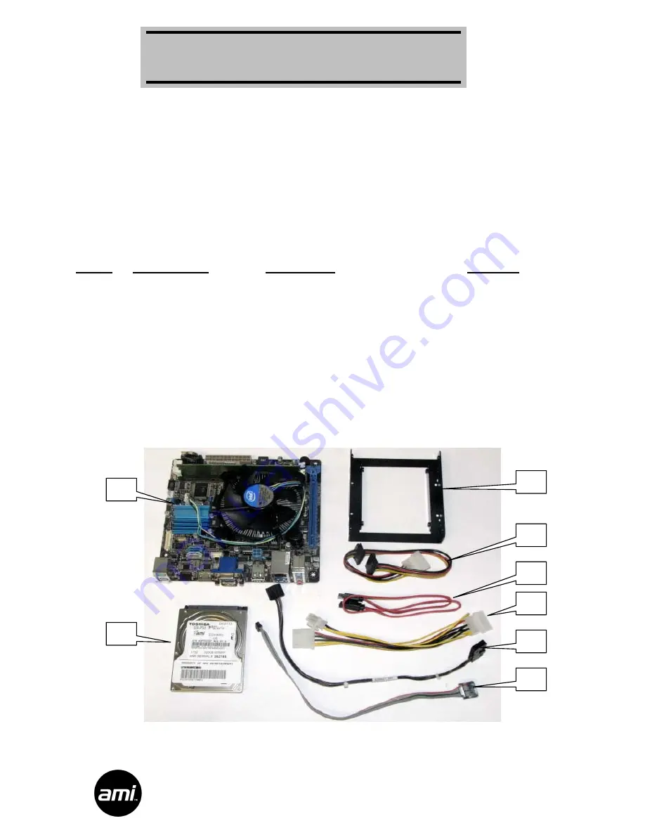
Parts Included with this Kit 
Item #


Part Number


Description


Quantity


  1 

40924214 

B75B Motherboard 

  2 

22219001 

SATA Hard Drive (US) 

  3 

40980802 

Bracket SATA Mounting Adapter 

  4 

22132253 

Cable HD SATA Power 

  5 

22132252 

Cable HD SATA/DATA 

  6 

34037946 

Harness ATX Power Adapter 

  7 

22132284 

Harness Front Panel View (B75B) 

  8 

22132280 

Cable Assembly COM to I/O 

  9 

80351604 

Screws #4-40 x ¼ Phillip (Not Shown) 

  10 

ST-06348 

Screws #6-32 x ¼ Phillip (Not Shown) 


These Instructions 


Figure 1 


Installation Instructions 

Summary of Contents for Ecast View B75B

Page 1: ...luded with this Kit Item Part Number Description Quantity 1 40924214 B75B Motherboard 1 2 22219001 SATA Hard Drive US 1 3 40980802 Bracket SATA Mounting Adapter 1 4 22132253 Cable HD SATA Power 1 5 22132252 Cable HD SATA DATA 1 6 34037946 Harness ATX Power Adapter 1 7 22132284 Harness Front Panel View B75B 1 8 22132280 Cable Assembly COM to I O 1 9 80351604 Screws 4 40 x Phillip Not Shown 4 10 ST ...

Page 2: ...rness connections to the View core computer assembly and remove the core computer from the jukebox 3 Remove the Ecast hard drive from the core computer This hard drive will not be reused Please return it to AMI 4 Disconnect all of the cables from the AMI View I O board Route all of the cables thru the access slots into the core computer chassis Remove the 4 screws holding the I O board and its cov...

Page 3: ...B motherboard must be shorted See Figure 3 Figure 3 6 Disconnect the 3 ribbon cables and the IDE hard drive cable they will not be reused Disconnect the 20 pin ATX power supply connector as shown in Figure 4 7 Remove the 4 screws holding the motherboard and the I O Shield to the core computer chassis The motherboard and the I O Shield will not be reused Figure 4 IDE CABLE RIBBON CABLES 20 PIN POWE...

Page 4: ... of the B75B motherboard See Figure 5 11 Connect the 20 pin ATX power supply connector to the B75B motherboard Locate the ATX 4 Pin Adapter Harness labeled 34037946 Item 11 Connect the 4 pin female housing to the 4 pin male housing of the ATX power supply Connect the 4 pin male housing to the B75B motherboard as shown in Figure 5 12 Connect the SATA DATA Hard Drive cable Item 5 to the SATA connect...

Page 5: ...I I O board cover with the same screws removed in Step 4 15 Secure the SATA hard drive 22219001 Item 2 to the SATA Mounting Adapter Bracket 40980802 Item 3 using the 4 4 40 x 1 4 screws 80351604 Item 9 as shown in Figure 6 Figure 6 16 Install the adapter bracket and hard drive assembly to the Computer Core with 4 6 32 x screws ST 06348 Item 10 as shown in Figure 7 Connect the SATA power cable and ...

Page 6: ...nto the wall outlet then power up the jukebox to ensure the jukebox UI comes up This will take some time and may include one or more reboots 20 In order for the jukebox to connect to the AMI network the MAC address of the computer core must be entered into the AMI database and the jukebox will have to be added to your operating contract This will require a phone call to the AMI Tech Support line 1...

Page 7: ... Setup then touch Enable Extend Features 28 Using the on screen keypad enter the trigger code found on the Trigger Code Card then touch the Send Code button 29 In order for the coin switches to work properly you will have to adjust the coin setup on the Cash Management Song Pricing screen For View kits that were installed in old Rowe CD jukeboxes with 4 coin acceptors use the coin setup shown in F...

Page 8: ...Page 8 of 8 26683851 REV A ...

Reviews: