


41
IEEE-488 Communication Option
IEEE-488 Command Set Reference
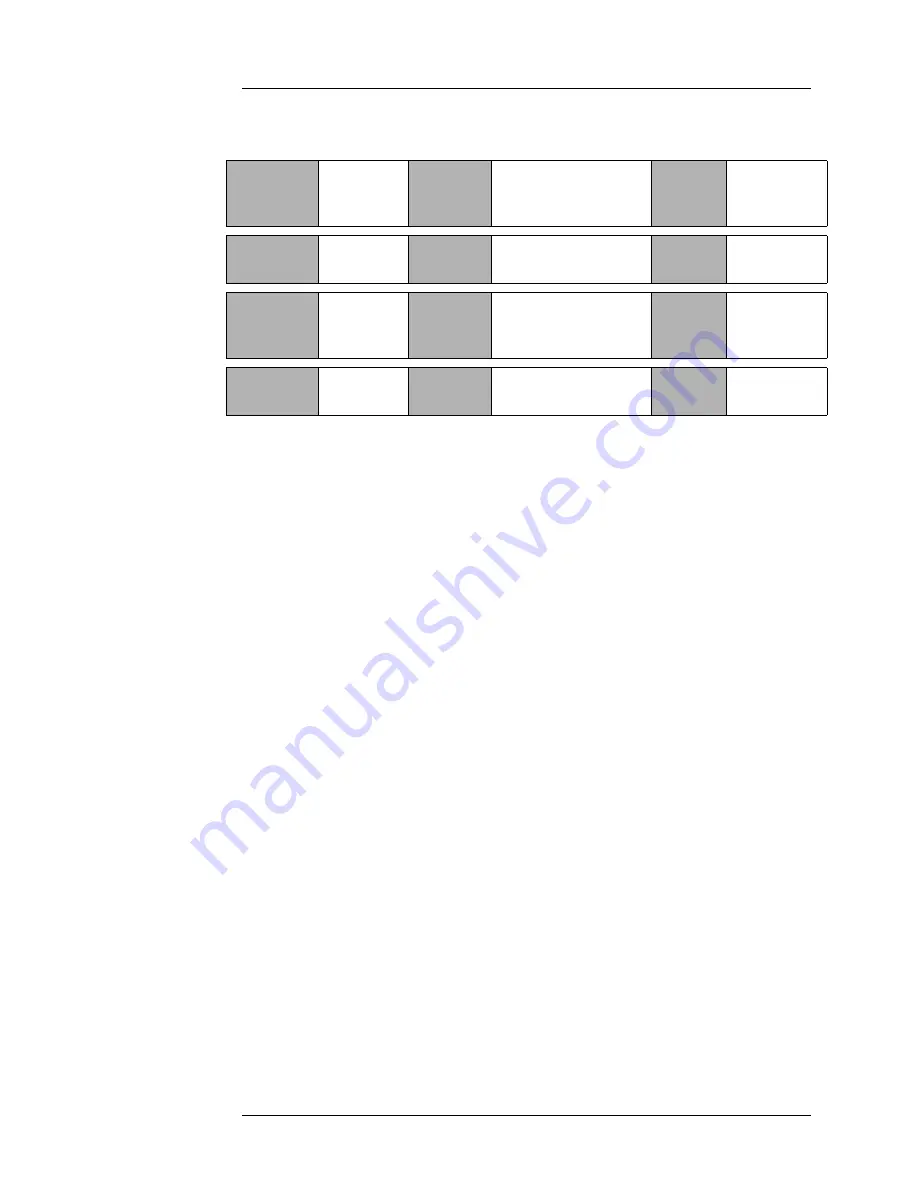
Commands for controlling the units of measurement
The CM command sets the units of measurement to centimeters and the INCH
command selects inches. The PERCENT command sets the units of measurement to
the percentage of the active sensor length that is immersed in liquid. The units of
measurement selected through the IEEE-488 interface are controlled independently
from the units mode toggle switch used for controlling the front panel display. The
default units are centimeters when the Model 186 is first powered on. The last unit
command remains in effect until the unit is powered off. The setting is not saved in
permanent memory. The UNIT command returns a one character value (and
termination) indicating the current units—C for centimeters, I for inches, or % for
percentage.
Command:
CM
Function:
Sets the units of
measurement to
centimeters
Returns:
CM
Command:
INCH
Function:
Sets the units of
measurement to inches
Returns:
INCH
Command:
PERCENT
Function:
Sets the measurement
to % of active sensor
length
Returns:
%
Command:
UNIT
Function:
Returns the current
units in use
Returns:
C, I, or %
Summary of Contents for 186
Page 3: ...2 Introduction ...
Page 13: ...12 Installation Configuring power ...
Page 23: ...22 Calibration Approximate Calibration ...
Page 29: ...28 Operation Sensor contamination ...
Page 37: ...36 RS 232 Communication Data Logger Option Error Codes ...
Page 47: ...46 IEEE 488 Communication Option Serial Poll Status Byte ...
Page 55: ...54 Virtual Instrument Operation Running multiple GPIB devices ...
Page 65: ...64 Index ...


