background image

Page 

32

 of 

33


08011 - X2 VDR and S-VDR System Operation Guide Iss01 Rev03 

Warranty Form 

 
AMI Marine Warranty; (abbreviated, full version on request) 
The Warranty Period is 24 months from date of dispatch, unless an alternative period has been otherwise agreed in writing. 
The first 12 months covers parts and on-board labour (travel and accommodation is not covered), the second 12 months covers parts 
only. 
 
Warranty covers parts that have failed due to a manufacture defect and does not cover shipping or associated charges 
 
This warranty shall only apply where the REGISTRATION CARD supplied with the goods has been properly completed and returned to 
AMI within the period of 21 days from installation. 
 
The registration form can also be downloaded from the AMI Marine website 

www.amimarine.com


Returns Procedure; 

Send an email RE: REQUEST FOR RETURN AUTHORISATION to 

[email protected] 


Please do NOT return items until a Return Authorisation Number has been issued. 
 

Documents to be included; 

A copy of the original INSTALLATION REPORT and a print out of your RETURN MATERIAL AUTHORISATION INFORMATION EMAIL, 
and enclose both in the return package. 
 
Be sure to pack the returning product securely and according to carrier instructions. Damage incurred during return shipping due to 
inadequate protection will render the item ineligible for return, repair, or exchange under the Warranty Terms. Items not received by AMI 
Marine, will not be credited.  
 
MOST authorised returns should be returned to the address below - however there are some exceptions, so DO NOT ship to this address 
without first reviewing your RETURN AUTHORISATION INFORMATION EMAIL for applicable return instructions: 
 
AMI Marine Limited 
Unit 9 Crosshouse Centre 
Crosshouse Road 
Southampton 
Hants 
SO14 5GZ 
UK 
 
A full explanation of AMI Marine Limited warranty conditions can be found on our web site or requested via email. 
 
 
* Terms of Service and Policies are subject to change without notice.  


------------------------------------------------------------------------------------------------------------------------------------------------------------------ 


Please complete and return to AMI Marine either by post to the above address or by email to [email protected] 


Warranty Registration Form


Model Number 


Serial Number 


Date of Purchase 


Vessel Name 


IMO Number 


Summary of Contents for X2

Page 1: ...X2 VDR S VDR Voyage Data Recorder System Operation Guide www amimarine com ...

Page 2: ...ations and IEC standards COPYRIGHT Copyright AMI Marine Limited 2019 All rights reserved No part of this publication may be reproduced transmitted transcribed translated or stored in any form or by any means without the written permission of AMI Marine Limited Technical details contained in this publication are subject to change without prior notice ...

Page 3: ...ction and Overview 9 Main Application and User Interface 11 Switching ON 11 HOME Screen 13 VIDEO Screen 14 AUDIO Screen 16 NMEA Screen 18 CAPSULE Screen 20 POWER Screen 22 System Test 24 EVENT LOG Screen 25 Incident Marker 26 Consumables Notifications 27 Consumables Due 27 Consumables Over Due 28 System Maintenance Schedule 29 Document Issue Details 30 Warranty Form 32 ...

Page 4: ... it is essential to work on the equipment with power connected work must only be undertaken by qualified personnel who are fully aware of the danger involved and who have taken adequate safety precautions to avoid contact with dangerous voltages HEALTH HAZARD 4 This equipment may contain materials which produce toxic fumes when ignited 5 The inhalation of dust and fumes or any contact with lubrica...

Page 5: ...Page 5 of 33 08011 X2 VDR and S VDR System Operation Guide Iss01 Rev03 ...

Page 6: ...cient detail to enable the bridge team to identify and address the caution condition No acknowledgement is required and the caution should be automatically removed after the condition is rectified Combined EPIRB VDR capsule Single unit which meets all the requirements of a satellite EPIRB as required by the carriage requirements of SOLAS IV and all the requirements of a VDR as required by the carr...

Page 7: ... record duration and has a readily accessible interface for downloading the stored data Playback equipment Any data medium with the playback software the operational instructions and any special parts required for connecting a commercial off the shelf laptop computer to the VDR Playback software Copy of the software program to provide the capability to download the stored data and play back the in...

Page 8: ...uid Crystal Display LED Light Emitting Diode LTRM Long Term Recording Medium MEU Main Electronics Unit MIC Microphone Unit MMSI Maritime Mobile Service Identity NMEA National Marine Electronic Association OS Operating System PC Personal Computer PDC Protective Data Capsule PoE Power Over Ethernet RADAR Radio Detection and Ranging ROV Remotely Operated Vehicle RTD Real Time Display SAR Search and R...

Page 9: ...ders installed on or after 1 July 2014 and conforming to performance standards not inferior to those specified in the annex to resolution A 861 20 as amended by resolution MSC 214 81 for systems installed prior to 1st July 2014 Main Electronics Unit MEU MEU 0017 The MEU has a key locked front door for secure access and a tamper switch ensure that any access to the internal circuitry of the MEU is ...

Page 10: ...icrophones MIC 0005 External MIC 0006 Internal The X2 microphones have been designed with high quality audio and easy installation in mind Using noise reducing 600Ω balanced audio for the clearest possible recording the audio clarity is second to none The built in auto test ensures all microphones are functioning correctly giving a visual indication on the TSM in the event of a failure External mi...

Page 11: ...ons Power LED This will illuminate when the key is turned to the ON position Recording LED This will illuminate when the X2 application is running Fault LED Only illuminates when there is a hardware fault or the door is open Download Indicates when a Download has been initiated Turning the key switch from the vertical ON position through 90 degrees clockwise to the horizontal position the system w...

Page 12: ...R System Operation Guide Iss01 Rev03 Once the system has completed the boot sequence the HOME screen will be displayed as below Pressing one of the tabs on the navigation menu at the left of the screen will open the corresponding screens ...

Page 13: ...Install Date Date of system installation commissioning Last Survey Date of last successful Annual Performance Test Vessel name Vessel s current name IMO number Vessel s IMO number MMSI number Vessel s IMO number Service contact details Contact details for the manufacturer The UTC date and time will be automatically updated from the received GPS data If the GPS data is not received or is lost then ...

Page 14: ...ture Two more capture cards are available on request for additional image capture such as ECDIS where the ship s ECDIS does not have an option for image over Ethernet Within the Video page thumbnails of the RADAR ECDIS video can be seen showing the current images being captured User Control Tapping the individual thumbnail will allow the chosen image to fill the window ...

Page 15: ...is raised the message NO CAPTURE CARD will be displayed the VIDEO status side bar itself will flash YELLOW Once acknowledged the VIDEO status side bar will stop flashing but remain YELLOW the alert panel will remain YELLOW until the issue is cleared The red FAULT LED on the MEU door will also illuminate until the fault is cleared If an ECDIS which is connected by IEC 61162 450 and is switched OFF ...

Page 16: ... allocated to the ship s VHF radios The microphones have a built in self test which will be periodically automatically tested or on demand as part of the System Test or individually The self test is undertaken by way of a beep test which will be heard via each individual microphone during the automatic and manual self tests The screen above shows each channel s received audio level and the current...

Page 17: ... is well YELLOW indicates that there has been a prolonged low audio level or that the audio test has failed There is no self test for the VHF audio so the indication will always be GREEN Once the audio level has been tested and is an acceptable level the indication will revert to green User Control Tapping the microphone status indicator will run a test on that individual channel ...

Page 18: ...red to monitor up to 50 NMEA sentences simply adding the expected NMEA sentence header into the respective channel of the configuration program By tapping an NMEA sentence header the monitor window will now only display the sentence with that specific header The selected NMEA header will turn bold and the description of the NMEA being monitored is now displayed The below example the VDVBW sentence...

Page 19: ...the NMEA status side bar will stop flashing but remain YELLOW the header icon will remain YELLOW until the issue is cleared Only when the data is received again will the header icon will revert back to GREEN User Control Tapping on an individual NMEA header found in the top window will filter the incoming data to show only the chosen NMEA data in the streaming window The selected NMEA header will ...

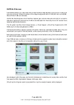
Page 20: ... a Float Free Capsule and a 1TB SSD Long Term Recording Medium LTRM The fixed and float free capsules operate in the same manner as a network hard disc drive They are connected to the system s internal network via the six way connector on the Terminal Board Each capsule will store a minimum of 48 hours data on their internal memory which will overwrite itself on a first in first out basis FIFO The...

Page 21: ...h device Tapping any of the pie charts returns to the main capsule screen If the External Storage optional extra has been purchased and installed then an External Graphic will be displayed User Control Tapping the screen will open the Disk Usage Information display Should either capsule show loss of connection tapping the capsule icon will remap the capsule to resume correct operation ...

Page 22: ...03 POWER Screen On this screen the Mains Power and UPS are monitored in the event of a failure If the Mains Power should fail the indication will turn YELLOW and the system will start a 2 hour countdown to switch OFF Note that on the MEU the red FAULT LED will illuminate ...

Page 23: ...ES icon shows a caution then this indicates that the batteries are not charging and a service centre should be notified User Control Pressing the System Test will bring up a prompt Press Again for System Test Pressing the System Test a second time will begin the full system test sequence ...

Page 24: ...em Operation Guide Iss01 Rev03 System Test Also on the POWER Screen this is where a system test is initiated Tap the button and the System Test will pop up tap again to initiate the System Test The test function will be inhibited for 2 minutes ...

Page 25: ...ss01 Rev03 EVENT LOG Screen The above screen shot shows the event log Results of a system test will be highlighted in blue On this page you can review all events You can select the search parameters by Date Hour or Priority by selecting the relevant drop down box ...

Page 26: ...ppear and say Press again to log incident Tap again to place an incident marker ion the system log file The Incident Marker icon will go green to acknowledge logging of the incident The Incident Marker can be accessed from any screen An Event marker will be shown in RED The event is saved in the Event Log file so that during download and playback the incident can be easily located ...

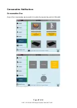
Page 27: ...Page 27 of 33 08011 X2 VDR and S VDR System Operation Guide Iss01 Rev03 Consumables Notifications Consumables Due If any of the consumables are due within 3 months the relevant box will turn YELLOW ...

Page 28: ... Guide Iss01 Rev03 Consumables Over Due If any of the consumables are overdue the relevant box will turn RED If any of the consumables have gone past their due date the Side indication bar will also flash YELLOW and the event will be added to the Log File ...

Page 29: ...oaded data 2 Year Check The following must be conducted by an AMI authorised inspector engineer Annual Performance Test APT Replace MEU system fan Replace hydrostatic release unit HRU 3 Year Check The following must be conducted by an AMI authorised inspector engineer Annual Performance Test APT Replace fixed capsule acoustic beacon battery 4 Year Check The following must be conducted by an AMI au...

Page 30: ...ses intended by the manufacturer any deviation from this will void the warranty of the product NOTE All alterations must be verified by re authorisation and approval of the complete document Document Issue Date Modification Number where applicable Brief Record of Change and Reason for Change Iss01 Rev00 23 01 19 Original Issue Iss01 Rev01 18 03 19 Update of Model Number X2 and correction of some w...

Page 31: ...Page 31 of 33 08011 X2 VDR and S VDR System Operation Guide Iss01 Rev03 This page Intentionally Blank ...

Page 32: ...e included A copy of the original INSTALLATION REPORT and a print out of your RETURN MATERIAL AUTHORISATION INFORMATION EMAIL and enclose both in the return package Be sure to pack the returning product securely and according to carrier instructions Damage incurred during return shipping due to inadequate protection will render the item ineligible for return repair or exchange under the Warranty T...

Page 33: ...Page 33 of 33 08011 X2 VDR and S VDR System Operation Guide Iss01 Rev03 This page Intentionally Blank ...

Reviews: