background image

Installation


AngelShark 

Internal M.2 PCIe SSD Expansion Carrier Board for Apple Mac Pro (Late 2013) 

 Hardware Manual, Revision 1.0 


Page 10


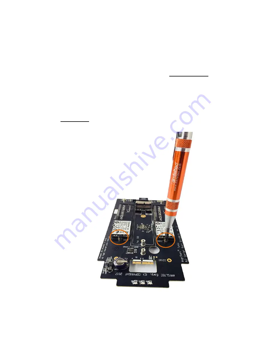
Mounting your desired M.2 PCIe Module(s) 


7)  Lay 

the

 Carrier Board (item #1) flat on your table for easier access 


8)  

Use slots “M.2 PCIe Module” #1 and/or #3, not the center slot. 


9)  

Slide your desired M.2 PCIe Module(s) directly into the carrier board’s 

connector(s). 
 

10)  Use the screwdriver with Phillips #1 bit to insert a mounting screw 

(item #5), as shown, to secure each SSD module. 

IMPORTANT:  DO NOT mount the original Mac PRO SSD module in the 

center slot yet. 


Summary of Contents for AngelShark Series

Page 1: ...ww amfeltec com Copyright 2017 Amfeltec Corp 25 Valleywood Dr Unit 2 Markham ON L3R 5L9 AngelShark Internal M 2 PCIe SSD Expansion Carrier Board for Apple Mac Pro Late 2013 Hardware Manual November 1 2017 Revision 1 0 ...

Page 2: ... 2 3 Features 5 3 1 Features 5 3 2 Carrier board SSD modules connection 5 4 Installation 7 4 1 Carrier board installation 7 5 Hardware Description 14 5 1 LEDs 14 5 2 Connectors 14 6 Appendix A Legal Info 15 7 Appendix B Limited Warranty 16 Figures Figure 1 All parts included in the package 3 Figure 2 AngelShark Carrier Board top 4 Figure 3 AngelShark Carrier Board bottom 4 Figure 4 SSD modules to ...

Page 3: ...oration 1 2 Feedback AMFELTEC Corporation makes every effort to ensure that the information contained in this document is accurate and complete at time of release Please contact AMFELTEC if you find any errors inconsistencies or have trouble understanding any part of this document To provide your feedback please send an email to support amfeltec com Your comments or corrections are greatly valued ...

Page 4: ...ot cost effective The AngelShark Carrier Board goes between the Mac and the original SSD Module while allowing for expansion with up to two more M 2 PCIe SSD modules user s choice The Carrier Board supports any M 2 PCI Express M key SSD modules with standard lengths 2260 2280 or 22110 2 2 System requirements Apple Mac Pro Later 2013 2 3 Package Contents Carrier Board package depending on the SKU p...

Page 5: ...iption AngelShark Internal M 2 PCIe SSD Expansion Carrier Board for Apple Mac Pro Late 2013 Hardware Manual Revision 1 0 Page 3 7 Apple SSD additional Heat Sink 2 4 Figures Figure 1 All parts included in the package ...

Page 6: ...escription AngelShark Internal M 2 PCIe SSD Expansion Carrier Board for Apple Mac Pro Late 2013 Hardware Manual Revision 1 0 Page 4 Figure 2 AngelShark Carrier Board top Figure 3 AngelShark Carrier Board bottom ...

Page 7: ... storage capacity by facilitating installation of additional M 2 PCIe SSD modules Supports up to two 2 M 2 PCI Express add in SSD modules M key x4 PCI Express connection to each M 2 module circuit x4 PCI Express connection to Apple SSD circuit Supports PCI Express Gen 3 8 0 Gbps operation Meets PCI Express 2 1 and M 2 1 1 Specifications Dimensions 178mm x 65mm RoHS compliant ...

Page 8: ...lShark Internal M 2 PCIe SSD Expansion Carrier Board for Apple Mac Pro Late 2013 Hardware Manual Revision 1 0 Page 6 3 2 Carrier Board SSD modules connection Figure 4 SSD modules to Carrier Board connection diagram ...

Page 9: ...le Mac Pro Late 2013 Hardware Manual Revision 1 0 Page 7 4 Installation 4 1 Carrier Board Installation IMPORTANT Unplug your Mac from electrical source Opening your Mac 1 Slide the highlighted switch to the unlock position 2 Lift the outer casing off of the Mac and set it aside ...

Page 10: ...er with Torx T8s bit item 2 to remove the black screw that secures the Mac SSD module in place original Set the black screw aside 4 Lift the black original Mac SSD module up until it pops out Set it aside 5 Use the screwdriver with Torx T8s bit item 2 to remove the two power screws top right corner These screws are no longer required because they will be replaced with power standoffs items 3 4 ...

Page 11: ...AngelShark Internal M 2 PCIe SSD Expansion Carrier Board for Apple Mac Pro Late 2013 Hardware Manual Revision 1 0 Page 9 6 Use the screwdriver with Slotted bit to carefully insert the power standoffs item 3 as shown ...

Page 12: ...rrier Board item 1 flat on your table for easier access 8 Use slots M 2 PCIe Module 1 and or 3 not the center slot 9 Slide your desired M 2 PCIe Module s directly into the carrier board s connector s 10 Use the screwdriver with Phillips 1 bit to insert a mounting screw item 5 as shown to secure each SSD module IMPORTANT DO NOT mount the original Mac PRO SSD module in the center slot yet ...

Page 13: ...hark Carrier Board 13 Carefully insert the carrier board directly into the Mac PRO PCIe slot until it pops into place as shown 14 Align the carrier board s yellow hole in the center with the appropriate Mac Pro hole behind it 15 Use the screwdriver with T8s bit item 2 to insert the original black screw which you removed in Step 3 as shown DO NOT TIGHTEN ...

Page 14: ...2 PCIe SSD Expansion Carrier Board for Apple Mac Pro Late 2013 Hardware Manual Revision 1 0 Page 12 16 Use the screwdriver with Phillips 000 bit to carefully insert the two power screws item 4 and tighten them 17 Tighten screw in Step 15 ...

Page 15: ... Manual Revision 1 0 Page 13 Mounting the original Mac Pro SSD Module on the carrier board s center slot 18 Gently slide the module directly into the carrier board s center connector until it pops into place 19 Use screwdriver with Phillips 1 bit to insert mounting screw item 5 as shown to secure the module ...

Page 16: ...g a heat sink item 7 to cover the M 2 SSD Module 20 IMPORTANT Remove the plastic tape to expose the adhesive side of the heat sink item 7 21 Take care to align the three mounting holes as shown when placing the heat sink on the module Use screwdriver with Phillips 1 bit to insert three 3 mounting screws item 5 as shown to secure the heat sink ...

Page 17: ...sion 1 0 Page 15 Attaching a heat sink item 6 to cover the original Mac SSD Module 22 Remove the plastic tape to expose the adhesive side of the heat sink item 6 23 Take care to stick the heat sink as shown in the top portion of the module as shown on the picture below IMPORTANT Ensure the ridges are vertically aligned ...

Page 18: ...ard for Apple Mac Pro Late 2013 Hardware Manual Revision 1 0 Page 16 You may now carefully return the outer case into place performing steps 1 2 in reverse You may now also connect your Mac to an electrical source and any of your peripherals as desired and power it on ...

Page 19: ... status indication Status 2 D21 Green Carrier board status indication Status 3 D1 Blue Carrier board status indication 5 2 Connectors Table 2 Carrier Board connectors Ref Des Type Usage U3 Connectors Upstream male connector for connection to Mac Pro upstream connection J1 Connector For original Apple SSD module connection Module 2 U13 M 2 connectors M key M 2 add in module connection Module 1 U14 ...

Page 20: ...ision 1 0 Page 18 6 Appendix A Legal Info Copyrights and Trademarks 2017 AMFELTEC Corp All rights reserved AMFELTEC is a trademark of AMFELTEC Corporation Apple Mac and Mac Pro are trademarks of Apple Inc registered in the U S and other countries Other marks may be the trademark or registered trademark property of their owners ...

Page 21: ...ause significant injury to humans AMFELTEC expressly disclaims liability for loss of profits and other consequential damages caused by the failure of any product which would cause interruption of work or loss of profits such as shipboard or military attachment THIS LIMITED WARRANTY IS IN LIEU OF ALL OTHER WARRANTIES EXPRESSED OR IMPLIED THE WARRANTIES PROVIDED HEREIN ARE BUYER S SOLE REMEDIES IN N...

Reviews: