501 (LH) 502 (RH) EZ Table Assembly
PARTS LIST
1:
Top 15” x 30”
5:
1/4-20 Nut
(N01)
2:
1/4 - 20 x 20” Bolt
(BT10)
6:
Column
(050007)
►►
WARNINGS
◄◄
3
1/4 x 3/8 Zinc SMS Screw
(SC12)
77
Base
(Left 050037)
Base (Right 050036)
This Table is to be used with heavier chairs and couches.
4:
Trip Handle
(101044)
8:
Top Bracket
(101019)
Incorrect positioning of table base (#7) under the chair or couch may result in
the table tipping over
. (R
ef. Assembly step 1)
California Prop. 65
Warning: The items and packaging in this shipment contains
chemicals known to the state of California to cause cancer, birth
defects or other reproductive harm.
*This product meets or exceeds all federal safetyand environmental
regulations
Tools
►
CAUTION--SPRING LOADED ASSEMBLY
◄
Phillips screwdriver
Do not remove the black shipping screw before completing Assembly steps
1- 5. Removing the shipping screw before this can result in spring damage.
(2) 7/16” wrenches
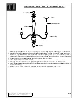
ASSEMBLY INSTRUCTIONS
Product is NOT! to be used as a lift assist or to hold more than 25 lbs.
1
Place the base
(#7)
under the left side of chair with the magazine
rack opening facing the rear of chair. Place the front left leg of the
chair on the positioning pad
(#8)
located near the magazine rack.
2b
Stand the Column
(#6)
on end, making sure the Trip Rod is visible
in the rectangular tube but not protruding out of the top, as shown
in
Fig. 1
. If necessary, shake the Column
(#6)
until the rod drops.
3
Insert Trip Handle
(#4)
into the Column
(#6)
with the rounded side
up. Be sure that the Trip Handle
(#4)
rests on top of the rod inside
the Column foot
(#6)
.
Fig. 1
4
Place the Top
(#1)
on a flat surface
,
with the Top Bracket
(#8)
facing upward. Then, while holding the Trip Handle
(#4)
in place
so it doesn’t fall out, insert the Column
(#6)
into the Top Bracket
(#8)
. Align the holes in the Column foot
(#6)
, the Trip Handle
(#4)
and the Top Bracket
(#8)
. Install both bolts
(#2)
and both nuts
(#5)
thru these aligned holes with the two (2) 7/16” wrenches.
Fig. 2
!
!
!
!