Ametek Sorensen Asterion DC Series Operation Manual Download Page 119

Asterion DC Series 

Calibration  

M330460-01  Rev D 


3-35 


Figure 3-86.


System Settings Screen (Status) 
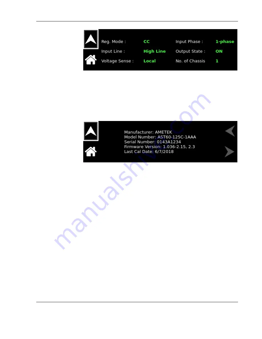


Firmware


Displays information about the configuration of the power   

Version


source.  It  has  information  such  as  manufacturer,  model  number, 
serial  number,  firmware  version  and  Last  Calibration  Date.    This 
information helps identify the unit

Refer to Figure 3-87. 


Figure 3-87.  System Settings Screen (Version) 


Summary of Contents for Sorensen Asterion DC Series

Page 1: ...M330460 01 Rev D 1 Asterion DC Series Operation Manual...

Page 2: ...Contents Asterion DC Series ii This page intentionally left blank...

Page 3: ...ve owners and are used herein for identification purposes only Notice of Copyright M330460 01 Asterion DC Series Operation Manual 2021 AMETEK Programmable Power Inc All rights reserved Exclusion for D...

Page 4: ...e instructions of AMETEK is opened modified or disassembled in any way without AMETEK s consent or is used in combination with items articles or materials not authorized by AMETEK The Buyer may not as...

Page 5: ...wer ground lines including those to application and maintenance equipment must be grounded properly for both personnel and equipment safety Always ensure that facility AC mains input is de energized p...

Page 6: ...ing Allow to cool before servicing DO NOT TOUCH Touching some parts of the instrument without protection or proper tools could result in damage to the part s and or the instrument TECHNICIAN SYMBOL Al...

Page 7: ...nst harmful interference when the equipment is operated in a commercial environment This equipment generates uses and can radiate radio frequency energy and if not installed and used in accordance wit...

Page 8: ...These models have been designed and tested to meet the Electromagnetic Compatibility Directive 2014 30 EU and the Low Voltage Directive 2014 35 EU In addition these models have been found compliant wi...

Page 9: ...e Specifications 1 12 1 2 10 Output Transient specifications 1 15 1 2 11 Remote Sense 1 16 1 2 12 Remote Analog Programming Interface Characteristics 1 17 1 2 13 Output Isolation 1 18 1 2 14 Remote Co...

Page 10: ...0 2 14 6 EtherCAT Interface Optional 2 42 3 OPERATION 3 1 3 1 Front Panel Display Menu and Functionality 3 1 3 1 1 Power Up Screens 3 1 3 1 2 Home Screen Top Level Menu 3 2 3 1 3 Dashboard Screen Top...

Page 11: ...mote Power Programming by Voltage Source 3 55 3 6 3 Remote Power Programming by 4 20mA Source 3 55 3 7 Remote Overvoltage Programming 3 56 3 8 Remote Output On Off Control 3 56 3 8 1 Remote Output ON...

Page 12: ...11 Remote Analog Programming Interface Connector Pin Out 2 37 Table 2 12 RS 232C Interface Connector Type 2 38 Table 2 13 RS 232C Interface Connector Pinout 2 38 Table 2 14 USB Interface Connector Typ...

Page 13: ...Connector 2 23 Figure 2 13 DC Output Busbar 2 23 Figure 2 14 Bus Bar Dimensions 2 24 Figure 2 15 Remote Sense Connector 3 Pin models 2 25 Figure 2 16 Remote Sense Connector 8 Pin models 2 25 Figure 2...

Page 14: ...assis 3 15 Figure 3 32 Source in Follower Mode Screen 3 16 Figure 3 33 Power ON Settings Menu Screen 1 3 16 Figure 3 34 Power ON Settings Menu Screen 2 3 16 Figure 3 35 Power ON Settings Menu Screen 3...

Page 15: ...0 Figure 3 76 Configure Analog Mode Screen 3 31 Figure 3 77 Analog Reference Mode Screen 3 31 Figure 3 78 Voltage Reference Mode Screen 3 31 Figure 3 79 Current Reference Mode Screen 3 32 Figure 3 80...

Page 16: ...e 3 53 Figure 3 106 Remote Voltage Programming Using 4 20mA Source 3 53 Figure 3 107 Remote Power Programming Using Resistance 3 54 Figure 3 108 Remote Power Programming Using 0 10 VDC Source 3 55 Fig...

Page 17: ...an intuitive touch screen interface placing that power at your fingertips Centralized control and unparalleled modularity make Asterion the most adaptable platform on the market Its groundbreaking ca...

Page 18: ...orithm that combines the benefits of precise control over small parameter changes with quick sweeps through the entire range The Asterion DC Series is designed for testing today s complex electronics...

Page 19: ...INPUT VOLTAGE VAC C 90 264 VAC 1 ph Line to Neutral Only 1U up to 5kW models or 200 240 VAC Line to Line 3 phase Delta D 380 400 415 VAC Line to Line 3 ph 3ph Neutral Wye E 440 480 VAC Line to Line 3...

Page 20: ...ollowing conditions a Ambient temperature of 25 5 C after a 30 minute warm up and at fixed AC input line and load b DC output into a resistive load c Specifications values are valid from 5 of the full...

Page 21: ...10 Voltage V Current A Voltage V Current A 40 42 85 125 40 250 60 28 56 83 60 167 80 22 43 63 80 125 100 17 34 50 100 100 150 12 23 34 150 67 200 9 17 25 200 50 300 6 11 17 300 34 400 4 3 8 5 13 400 2...

Page 22: ...le Determination of the available voltage or current under your conditions can be calculated readily As an Example we will use the 5kW 60V 125A model AST60 125AR This unit can provide up to 125A from...

Page 23: ...Asterion DC Series Overview M330460 01 Rev D 1 7 Figure 1 2 Auto range Models Characteristics...

Page 24: ...ominal Rating DC or AC 50 Hz 60 Hz 400 Hz2 Input Frequency Range DC or AC 47 63Hz 360 440Hz2 Efficiency1 typical 89 for 1 7 kW 1U Models 90 for 3 4 kW and 5 kW 1U Models Power Factor1 typical 0 98 for...

Page 25: ...4 for Three Phase Input Models Hold Up Time1 typical 10 ms Isolation Voltage 1500VAC primary to earth 3000VAC on primary to SELV and Hazardous secondary to SELV isolation barriers THD Voltage 1 1 At f...

Page 26: ...ut current inlet and ambient does not exceed 40 C 2 Unit can operate at 5 kW if powered by greater than or equal to 30 A of input current inlet and ambient does not exceed 40 C 3 For 3 4kW performance...

Page 27: ...ated output voltage Current Output Measurement accuracy 0 2 of rated output current Power Output Measurement accuracy 0 3 of rated output power Voltage Output Measurement resolution 0 012 of full scal...

Page 28: ...100 300 20 120 400 40 300 600 60 300 3 4kW Fixed Range Models 1U Chassis Rated Voltage V Voltage Ripple Noise RMS mV1 Voltage Ripple Noise PK PK mV2 40 12 75 60 12 75 80 15 90 100 15 90 150 20 120 200...

Page 29: ...0 400 40 300 600 60 300 3 4kW Auto Range Models 1U Chassis Rated Voltage V Voltage Ripple Noise RMS mV1 Voltage Ripple Noise PK PK mV2 40 12 75 60 12 75 80 15 90 200 40 150 400 80 300 600 80 350 10kW...

Page 30: ...Voltage V Voltage Ripple Noise RMS mV1 Voltage Ripple Noise PK PK mV2 60 12 75 200 40 150 400 80 300 1 RMS ripple noise over 20 Hz to 300 kHz bandwidth is measured directly across the output terminal...

Page 31: ...s Full load1 Voltage Current Fall Time ms Full load3 Voltage Fall Time ms No load4 Transient response ms 5 40 20 50 1200 1 60 20 50 1500 1 80 25 60 2600 1 200 75 15 3500 2 400 100 200 4600 2 600 150 2...

Page 32: ...o with No load 5 Typical time to recover within 0 5 of rated output voltage for load step of 10 90 of rated output current 1 2 11 Remote Sense Maximum Line Drop Compensation1 40V Model 60V Model 80 60...

Page 33: ...e Current and Power Full Scale range 0 V to 10 V corresponds to 0 100 full scale output Minimum recommended Load 100 k typical Maximum Load 20 k Monitor accuracy 1 of full scale output Remote ON OFF C...

Page 34: ...User programmable digital inputs There is an Option to feed User Power to these digital outputs Voltage Rating Min 4 5V or User fed voltage minus 1 V User fed voltage can be of maximum 30 V Current M...

Page 35: ...stop bits 2 baud rate 9600 to 115200 handshake CTS and RTS Connector Subminiature D 9 contact receptacle IEEE 488 Option Parallel interface complies with IEEE 488 1 IEEE 488 2 and the SCPI command sp...

Page 36: ...Input Overcurrent Protection Internal fuses in each phase for fault isolation not user replaceable AC Input Undervoltage Protection Automatic shutdown for insufficient AC input voltage AC Input Transi...

Page 37: ...unt per ANSI EIA 310 D with front panel mounting flange brackets and chassis provisions for mounting rack slides slides and flange brackets handles options available Cooling Forced air cooling linear...

Page 38: ...Overview Asterion DC Series 1 22 This page intentionally left blank...

Page 39: ...oll free in North America 2 2 Contents of Shipment Depending on the model configuration and options selected for your Asterion Series power source the ship kit may include additional parts and accesso...

Page 40: ...TERM BLK 4P 41A 1KV PLG 7 62MM 1 Phoenix Contact 1709173 5330565 01R ASSY CONN 44P DSUB 1 AMETEK 5330565 01R 109 346 00 STRAIN RELIEF 3 4 NPT 25 485 1 Heyco Products 3460 MN M04K 07 NUT M4X0 7 KEPS S...

Page 41: ...and rear of the unit must be kept clear of obstruction and clearance must be maintained to allow unimpeded airflow The same consideration given to the side grilles will minimize internal temperature...

Page 42: ...7 12 Recommended rackmount kit installation instruction is as follows Reference Figure 2 1 Rack mounting 1U Models and Figure 2 2 Rack Mounting 2U Chassis 1 Install the chassis sections of the slides...

Page 43: ...Asterion DC Series Installation M330460 01 Rev D 2 5 Figure 2 1 Rack mounting 1U Models...

Page 44: ...Installation Asterion DC Series 2 6 Figure 2 2 Rack Mounting 2U Chassis...

Page 45: ...g located on the slides inward and pull the chassis forward To return the chassis back into the rack from full extension depress the flat steel spring located on the slides inward and push the chassis...

Page 46: ...View 1U Models w EtherCAT Option Figure 2 7 Rear Panel View 1U Models w GPIB Option and Figure 2 8 Rear Panel View 2U Chassis show the rear panel views of the power sources and locations of the rear...

Page 47: ...Asterion DC Series Installation M330460 01 Rev D 2 9 Figure 2 3 Installation Drawing Enhanced front panel version 1U Models...

Page 48: ...Installation Asterion DC Series 2 10 Figure 2 4 Installation Drawing Enhanced front panel version 2U Models...

Page 49: ...Asterion DC Series Installation M330460 01 Rev D 2 11 Figure 2 5 Rear Panel View 1U Models...

Page 50: ...Installation Asterion DC Series 2 12 Figure 2 6 Rear Panel View 1U Models w EtherCAT Option...

Page 51: ...Asterion DC Series Installation M330460 01 Rev D 2 13 Figure 2 7 Rear Panel View 1U Models w GPIB Option...

Page 52: ...Installation Asterion DC Series 2 14 Figure 2 8 Rear Panel View 2U Chassis...

Page 53: ...Asterion DC Series Installation M330460 01 Rev D 2 15 Figure 2 9 Rear Panel Protective Cover Installation 1U Models Output Co er Input Co er M E S uts la es...

Page 54: ...Installation Asterion DC Series 2 16 Figure 2 10 Rear Panel Protective Cover Installation 2U Models ut or Stra in e lie Strain elie M E S uts la es Output Co e r Input Co e r...

Page 55: ...disconnect device for the AC mains input must be installed so that it is readily accessible to the user WARNING A properly sized input overcurrent protection device must be installed at the AC mains i...

Page 56: ...1 MAC2 EtherCAT Option Modular connection for Optional EtherCAT for remote digital control see section 2 14 6 External digital interface GPIB IEEE 488 Option GPIB IEEE 488 Option connector for remote...

Page 57: ...current protection The Asterion DC Series power source has fuses at the AC input for fault protection These fuses are internal to the chassis and are not user accessible They provide fault isolation i...

Page 58: ...ith female contacts A ground connection must always be made to the utility earth protection ground using the AC Input connector pin or rear panel safety ground stud Name Type Range Function AC INPUT L...

Page 59: ...g torque is 1 1 Nm 10 lb in max Table 2 3 AC Input Connector Type CAUTION To prevent damage to the AC input mating connector follow torque specifications and if a wire ferrule is used ensure that it i...

Page 60: ...8VAC for 3 Phase inputs Exceeding the maximum AC input voltage could result in damage to the unit 2 9 DC input power connection The Asterion DC Series power source is also designed to operate with a D...

Page 61: ...Asterion DC Series Installation M330460 01 Rev D 2 23 Figure 2 10 300 400V Models DC Ouput Mating Connector Figure 2 12 300 400V Models DC Output Mating Connector Figure 2 13 DC Output Busbar...

Page 62: ...models 2U Bus bars with holes for 3 8 bolts on each terminal POS NEG 10 0 kW 20 200V models 2U Phoenix connector Table 2 4 DC Output Power Connections Manufacturer Low Current High Current Panduit P P...

Page 63: ...ar panel Figure 2 15 shows the connection to the supplied mating connector for the models equipped with a 3 pin sense connection and Figure 2 16 for models with the 8 pin sense connection Table 2 6 li...

Page 64: ...voltage feedback for output regulation Figure 2 15 and Figure 2 16 show the remote sense mating connector wiring Remote sensing is used to compensate for the voltage drop that occurs across the wires...

Page 65: ...ed unless crimp on lugs or ferrules are utilized that are approved for fine stranded cables 2 12 1 Wire Size The tables below will assist in determining the appropriate wire size for both the input an...

Page 66: ...hout overheating or causing insulation degradation It is important to power source performance to minimize IR voltage drop loss within the cable These losses have a direct effect on the quality of pow...

Page 67: ...1 t2 t1 The output power cables must be large enough to prevent the line voltage drop total of both output wires between the power source and the load from exceeding the remote sense capability as pre...

Page 68: ...o Figure 2 18 CAUTION Series connected supplies must also use the freewheel diode to prevent reverse biasing the output stages in conditions where one of the supplies has been shut down The sense lead...

Page 69: ...ming and External user control interface is located on the rear panel Figure 2 19 shows the rear panel view of the connector and Table 2 9 lists the connector type Table 2 10 shows the functions and T...

Page 70: ...Output Voltage Current and Power Full Scale range 0 V to 10 V corresponds to 0 100 full scale output Minimum recommended Load 100 k typical Maximum Load 20 k Monitor accuracy 1 of full scale output R...

Page 71: ...that can be enabled disabled from the power supply Two digital outputs can be controlled by giving appropriate signals on User programmable digital inputs There is an Option to feed User Power to thes...

Page 72: ...mming using a resistance connected to signal return Pin 18 0 5 k or 0 10k 0 100 of full scale output voltage 4 VPRG_VSOUR VPRG_4 20mA_SOUR ANALOG IN Remote control input for voltage programming using...

Page 73: ...R GND Return for Pin 30 USER_PWR 16 RTN_HV ISO GND Return for Pin 1 ON OFF_HV and Pin31 ON OFF_ISO 17 Not Used Not Used Not Used 18 RTN_PRG ANALOG GND Return for Pin 3 4 5 19 20 33 34 This control ret...

Page 74: ...s 1V whichever is higher Maximum current of 0 5A 28 RTN_UPWR POWER GND Return for Pin 24 25 26 27 29 RTN_AUX5 POWER GND Return for Pin 43 5V_AUX 30 USER_POWER POWER IN Optional User can connect betwee...

Page 75: ...d by user or state of pin 10 Output high state either min 5V or voltage on pin 30 USER_PWR minus 1V whichever is higher Maximum current of 0 5A 39 AUX5_EN DIGITAL IN Apply a high to enable output on p...

Page 76: ...re D Table 2 12 RS 232C Interface Connector Type Pin Name DCE Signal Direction 1 N C N A N A 2 TxD Transmit Data Output 3 RxD Receive Data Input 4 N C N A N A 5 Common N A N A 6 N C N A N A 7 RTS Requ...

Page 77: ...control refer to Figure 2 22 for view of connector Table 2 16 for connector type and Table 2 17 for pin descriptions A standard modular cable with an 8P8C modular plug should be used between the power...

Page 78: ...5 Transmit Receive Data 2 White with blue stripe White with blue stripe 6 Transmit Receive Data 1 Orange with white stripe or solid orange Green with white stripe or solid green 7 Transmit Receive Dat...

Page 79: ...put output bit 3 DIO3 Data input output bit 4 DIO4 Data input output bit 5 EOI End or Identify 6 DAV Data valid 7 NRFD Not ready for data 8 NDAC Not data accepted 9 IFC Interface clear 10 SRQ Service...

Page 80: ...plies have an optional EtherCAT interface that allows accessing most of the read and writing registers The registers that are available are listed in Table 2 20 Registers Available EtherCAT Interface...

Page 81: ...PDOs is set to floating point input DIGITAL PROGRAMMING MODE 1 To enable digital programming Table 2 21 Command Bits Required for EtherCAT Operation EtherCAT Process Data Objects PDOs and variables a...

Page 82: ...Installation Asterion DC Series 2 44 EtherCAT PDO Tree EtherCAT PDO Variables Table 2 22 EtherCAT PDOs and Variables...

Page 83: ...Asterion DC Series Installation M330460 01 Rev D 2 45 This page intentionally left blank...

Page 84: ......

Page 85: ...inally the Dashboard screen Refer to Figure 3 7 Figure 3 1 Splash Screen Figure 3 2 Power On Screen Displaying Model Version If output is enabled in Power ON Settings PONS screen refer to Figure 3 17...

Page 86: ...screen Each menu of a screen could be selected by tapping its associated selection field box through the touch screen or by selecting it with the rotary encoder and depressing clicking the rotary enco...

Page 87: ...Mode Regulation Mode Output state and OVP Over Voltage Protection MEASUREMENTS Provides measurement of output parameters Voltage Current and Power CONFIGURATION Provides setup of Power ON States PONS...

Page 88: ...setting is possible using the rotary encoder POWER Programs the power in constant power mode for power regulation in KW Real time setting is possible using the rotary encoder NOTE The unit will opera...

Page 89: ...yed Tapping numerical value keys the decimal point key or the polarity key selects them while the back arrow key erases the last entry To enter a negative value first enter the number then the minus s...

Page 90: ...Home Screen 1 of the front panel touch screen 2 Scrolling to the OUTPUT PROGRAM screen with the encoder and depressing the encoder switch The UP arrow button will return to the previously selected sc...

Page 91: ...or the output voltage Exceeding the OVP threshold will result in shutdown of the output and the output voltage programmed to zero refer to Figure 3 14 Figure 3 14 OVP Setting REGULATION Selects option...

Page 92: ...Voltage Output Current and Output Power the DC Output Voltage Output Current and Output Power The Measurements screen is shown in refer to Figure 3 18 Refer to Section 3 1 2 1 for navigating to Measur...

Page 93: ...the following fields Entry Description Volt Sets the start voltage for the ramp To Volt Sets the end voltage for the ramp Curr Sets the Current limit for the ramp Time Sets the time in seconds to reac...

Page 94: ...Figure 3 23 This shows that the supply is waiting for an active high pulse of 10ms on the MOLEX connector pin 8 TRIGGER_IN and pin 12 DIN_RTN to generate the Voltage Ramp Refer to Table 3 2 Analog Pro...

Page 95: ...Abort button Observe the voltage ramp signal using oscilloscope Clicking on the Abort button will abort the ramp Clicking on the Exit button will exit the Voltage Ramp screen Example 2 Creating a Vol...

Page 96: ...lt Sets the volt limit for the ramp Time Sets the time in seconds to reach from start current to end current Trigger Sets the trigger mode for the ramp In SW Software trigger mode the ramp is generate...

Page 97: ...generate the Current Ramp Refer to Table 3 2 Analog Programming Connector Designations and Functions for PIN details Figure 3 27 Current Ramp Screen HW Trigger Abort In SW trigger mode when Trigger Ra...

Page 98: ...Hardware Trigger mode Set the Curr to 10A Set the To Curr to 30A Set the Volt to 25V Set the Time to 10s Connect an appropriate load to the supply Select the Trigger mode as HW Hardware Click on Initi...

Page 99: ...tli Chassis menu allows the user to switch between parallel and series mode This option will be disabled on single chassis operation refer to Figure 3 30 This option will be enabled when two or more c...

Page 100: ...nnected in parallel or series refer to Figure 3 32 Figure 3 32 Source in Follower Mode Screen 3 1 7 2 POWER ON SETTINGS PONS The PONS Menu allows user to set the Power ON values and setup of power sup...

Page 101: ...efer to Figure 3 36 Figure 3 36 Power On Voltage Setting Current Sets the power on default current refer to Figure 3 37 Figure 3 37 Power On Current Setting Output State Sets the default output enable...

Page 102: ...Sense menu allows user to set the output voltage sense of the unit to either Internal or External refer to Figure 3 53 When External is selected as output sense voltage sense cables must be connected...

Page 103: ...mit refer to Figure 3 43 Figure 3 43 Current User Limit Power User Limit Sets the power on default value of the Power User Limit refer to Figure 3 44 Figure 3 44 Power User Limit Analog Ref Source Set...

Page 104: ...able Figure 3 46 Voltage Reference Mode Curr Ref Mode Sets the power on default value of the Current Reference Mode refer to Figure 3 47 When external Ref Source is selected as Resistive FSC Full Scal...

Page 105: ...er voltage Reference Mode refer to Figure 3 49 NOTE Resistive and 4 20mA source is not applicable to external OVP programming Figure 3 49 OVP Reference Mode Voltage Average Sets the power on default v...

Page 106: ...a method for protecting the load against damaging voltages currents and or power levels The User V I Limits menu has the following fields Entry Description Voltage Sets the upper user limit on the pr...

Page 107: ...of voltage readings to average together to reduce noise in the voltage readback Allows to set a value between 1 to 5 The value of 1 factory default provides the fastest response time in the readings b...

Page 108: ...V AUX not available on 1U chassis models when not equipped with optional isolated analog interface 3 1 8 Control Interface Screen The Control Interface screen provides the ability to configure the pow...

Page 109: ...1 8 1 RS232 Entry Description RS232 Settings Lists the configured Baud Rate Stop Bits Bits and Parity for the RS232 digital interface refer to Figure 3 57 and Figure 3 58 Figure 3 57 RS232 Home Screen...

Page 110: ...Figure 3 60 LAN Screen LAN SETTINGS Lists the configuration settings of the LAN interface Refer to Figure 3 61 Figure 3 61 LAN Screen Settings LAN CONFIGURE Sets parameter values and controls operati...

Page 111: ...in the range of 169 254 X X Where the X X in the last two octets are randomly generated Figure 3 63 LAN Screen DHCP Auto IP Enables or disable the Auto IP configuration when DHCP is ON Refer to Figure...

Page 112: ...Refer to Figure 3 67 Figure 3 67 LAN Screen IP Address Subnet Mask Sets the subnet mask for use in static IP configuration Refer to Figure 3 68 Figure 3 68 LAN Screen Subnet Mask Gateway Address Sets...

Page 113: ...ettings will be set to factory Default Refer to Figure 3 70 Figure 3 70 LAN Screen Restore Default Apply Now Applies the LAN settings to the supply Refer to Figure 3 71 Figure 3 71 LAN Screen Apply 3...

Page 114: ...e 3 73 Analog Screen Analog Mode Lists the configuration settings of the Analog Programming Settings interface Refer Figure 3 74 and Figure 3 75 Figure 3 74 Analog Mode Settings 1 Figure 3 75 Analog M...

Page 115: ...ference Mode refer to Figure 3 78 When Voltage reference mode is selected as External the Voltage setting field in Dashboard screen will be disabled and Voltage setting field in Dashboard will display...

Page 116: ...Figure 3 79 Current Reference Mode Screen Power Ref Mode Configures the Power Reference Mode refer to Figure 3 80 When Power reference mode is selected as External the Power setting field in Dashboard...

Page 117: ...m 1 through 30 refer to Figure 3 85 Also allows to turn On Off the Power ON Service Request Power On SRQ set to On causes a GPIB service request to be sent to the computer when the Power Supply is tur...

Page 118: ...shown in Figure Figure 3 84 Refer to Section 3 1 2 1 for navigating to System Settings Screen Figure 3 84 System Settings Screen Top Level Menu 1 Figure 3 85 System Settings Screen Top Level Menu 2 T...

Page 119: ...irmware Displays information about the configuration of the power Version source It has information such as manufacturer model number serial number firmware version and Last Calibration Date This info...

Page 120: ...Sets the brightness of the LCD backlight as a percentage of the maximum that is available the default setting is 70 Tapping on the Right or Left arrow buttons or selecting them with the encoder and c...

Page 121: ...screen is enabled Timeout Interval Selects the time in seconds for how long Dashboard screen must be inactive before the Default screen is displayed Figure 3 93 System Settings Screen Default Screen E...

Page 122: ...r during operation Refer to Figure 3 96 Pressing on View Faults will display all the Fault Warning description with an option to clear the Fault These warnings indicate description of Faults which has...

Page 123: ...correct the condition that caused the OVP prior to re enabling the output 3 1 11 Local Remote Screen This screen is displayed when operation is controlled by computer Pressing Set Local from Local Re...

Page 124: ...n the constant voltage mode 8 On the Dashboard screen rotate the rotary knob to select the Voltage text box in the Setting section Press the rotary knob to highlight the voltage value Rotate the rotar...

Page 125: ...of rated output by entering the in the Setting section on the Dashboard Screen This programs the Voltage above zero to enable supplying output voltage while in the constant current mode 6 On the Dash...

Page 126: ...of the maximum rated output of the supply On the Output Program screen rotate the rotary knob to set the OVP Press the rotary knob to highlight the OVP value Rotate the rotary knob anti clockwise unti...

Page 127: ...gulate to the Constant Power setting due to load conditions it will regulate either at the voltage or current limit depending on the load demand Refer to Figure 3 99 Figure 3 99 Constant Power Example...

Page 128: ...ame Analog Control connector J1 as the standard interface This option fully isolates remote control signals and allows control of units not connected to a common ground Control ground is isolated from...

Page 129: ...supply up to 500 VDC Signal return is Pin 16 RTN_HV 2 Not Used Not Used Not Used 3 VPRG_ISOUR ANALOG OUT Current source of 1 mA for remote voltage programming using a resistance connected to signal re...

Page 130: ...high output on pin 37 Up to 24V capable 3V max low 2 7V min high 12 RTN DIGITAL GND Return for Pin 7 8 9 10 11 12 13 ESTOP DIGITAL IN Short to Pin 14 to permit operation Internally tied to 5V through...

Page 131: ...lt Output high state either min 4 5V or voltage on Pin 30 USER_PWR minus 1V whichever is higher Maximum current of 0 5A 27 DIO_OUT2 POWER OUT Output low for CV or CC and high for CP Output high state...

Page 132: ...D Return for Pin 37 38 37 OUT_RY_ON POWER OUT User digital output cause to be assigned by user or state of pin 11 Output high state either min 5V or voltage on pin 30 USER_PWR minus 1V whichever is hi...

Page 133: ...SOUR and return to Pin 18 RTN_PRG An internal current source factory set at 1 mA from Pin 20 is utilized to drive the resistance This produces a transfer function for output current as follows Iout 1...

Page 134: ...to any voltage between 2V to 10V from front panel screen refer to Section 3 1 8 4 Default FSC voltage value is 10V where 10V corresponds to 100 output current The corresponding voltage programming co...

Page 135: ...tion is used for applications that require the output voltage be programmed controlled from a remote instrument An external resistance or external voltage source or 4 20mA source may be used as a prog...

Page 136: ...ming by Voltage Source The DC voltage source is connected between Pin 4 VPRG_VSOUR and the return Pin 18 RTN_PRG and Analog Reference source is selected as Voltage from the front Panel Refer to Figure...

Page 137: ...and select the Analog Reference Source as 4 20mA in front panel Refer to Figure 3 106 The transfer function for the output voltage will be as follows Vout I4 20mA 4 100 rated output voltage 16 with I...

Page 138: ...istance programming default coefficient for output power is 100 rated output power 5 k with input at Pin 34 PPRG_ISOUR and return to Pin 18 RTN_PRG An internal current source factory set at 1 mA from...

Page 139: ...s transfer functions for output power as follows Pout Vdc 100 rated output power 10 VDC with Vdc in volts or Pout Vdc 100 rated output power FSC VDC with Vdc in volts Figure 3 108 Remote Power Program...

Page 140: ...tput on off control may be accomplished by contact closure or through an opto isolated interface with external voltage sources AC DC or TTL CMOS 3 8 1 Remote Output ON OFF by Contact Closure Applicati...

Page 141: ...and 16 will turn on the power supply this interface is opto isolated from circuit common See Figure 3 112 and Figure 3 113 for connection requirements Figure 3 112 Remote Output On Off Using Isolated...

Page 142: ...interface cable 890 524 01 to connect the PAR OUT connector on the designated Leader power supply to the PAR IN connector on the second or Follower power supply Repeat connection between Leader CAN O...

Page 143: ...ins active for all units in parallel operation If the units are set to different OVP levels the paralleled system will trip according to the lowest setting For ease of use adjust the OVP levels for th...

Page 144: ...Calibration Asterion DC Series 3 60 Figure 3 114 Parallel Connection 3 Chassis...

Page 145: ...Asterion DC Series Calibration M330460 01 Rev D 3 61 Figure 3 115 Parallel Connection 2 Chassis...

Page 146: ...ositive terminal of the load 4 Connect the Negative output terminal of the Leader power supply to the Positive output terminal secondary unit Follower 5 Connect the Negative output terminal of the sec...

Page 147: ...earth ground This is limited by the isolation and creepage clearance distances internal to the power supply construction If a higher output voltage range is required contact the factory for availabil...

Page 148: ...Calibration Asterion DC Series 3 64 Figure 3 117 Series Connection...

Page 149: ...Asterion DC Series Calibration M330460 01 Rev D 3 1 This page intentionally left blank...

Page 150: ...practice Calibrate only as needed Reference Programming Manual for Calibration Procedure 4 1 2 Digital programming and readback calibration Refer to the Asterion DC programming manual for calibration...

Page 151: ...Asterion DC Series Calibration M330460 01 Rev D 4 3 This page intentionally left blank...

Page 152: ......

Page 153: ...itch Do not touch any circuits and or terminals that are energized 5 2 Preventive Maintenance WARNING The OFF position of the front panel power switch does not remove AC input from internal circuits o...

Page 154: ...e is any evidence of short circuits or arcing overheating or corrosion contact the factory for recommended service 5 3 Fuses There are no user replaceable components in the power supply Internal fuses...

Page 155: ...2 17 Inrush Current 1 8 Inspection 2 40 Installation 1 21 INSTALLATION 2 1 Isolation Voltage 1 8 1 9 LAN 1 19 LAN Connector 2 39 2 40 LAN Menu 3 26 3 29 3 30 Maintenance 5 1 Fuses 5 2 Preventive 5 1...

Page 156: ...mote Voltage Programming 3 51 3 54 Resistance Control 3 51 3 54 Voltage Source Control 3 52 3 55 RS 232C 1 19 RS 232C Connector 2 38 Safety Disconnect Device 2 17 Safety Ground Wire 2 17 Screens Warni...

Page 157: ...M330460 01 www powerandtest com This page intentionally left blank...

Reviews: