Asterion DC Multioutput ASA Series Operational Manual
M330516-01
2-9
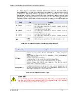
RS-232C connector
RS-232C connector for remote digital control;
see section 2.12.3.
External digital
interface
USB Connector
USB type B connector for remote digital control;
see section 2.12.4.
External digital
interface
Ethernet connector
Ethernet connector for remote digital control; see
section 2.12.5.
External digital
interface
Isolated Analog Interface
connector (Option)
User Analog Control interface; see section 2.12.1 User controller
GPIB (IEEE-488) (Option)
GPIB (IEEE-488) Option connector for remote
digital control.
External digital
interface
Table 2-2: Rear Panel Connector
No of
Channels
Voltage
Model
AC Input Option Code
Nominal Input
Voltage, Range
VAC
Maximum Input
Line Current, A
(RMS)
3
60V- 400 V
C - 3 Phase Input
200V - 240V
7.2
C- 1 Phase Low Line Input
100V - 132V
25
C- 1 Phase High Line Input
200V - 240V
12.5
D
380V - 415V
3.8
E
440V - 480V
3.2
2
60V- 400 V
C - 3 Phase Input
200V - 240V
4.8
C- 1 Phase Low Line Input
100V - 132V
16.7
C- 1 Phase High Line Input
200V - 240V
8.3
D
380V - 415V
2.5
E
440V - 480V
2.2
Table 2-3: Maximum Input Line Current
2.8
AC input power connection
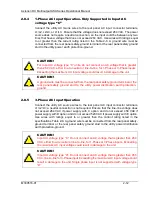
The Multioutput Asterion DC Series power source is designed to operate from 1-phase
or 3-phase input power, having 2 wire/3-wire plus ground, with nominal AC input
voltage (Refer Table 2-3), and 50/60 Hz input frequency. The AC input voltage range
is automatically selected by the unit at power-up; no user setup is required. Power
factor correction (PFC) provides high power factor, minimizing the required input
apparent power and current harmonic distortion. Refer to the specifications of Section
1.2 for AC input current requirements, and derating of output power as a function of
AC input voltage.
2.8.1
AC input overcurrent protection
The Asterion DC Multioutput Series power source has fuses at the AC input for fault
protection. These fuses are internal to the chassis and are not user accessible. They
provide fault isolation in case a failure occurs of internal components or wiring. A
suitable overcurrent protection device must be provided externally, within the system
installation, to protect the external wiring and interconnects.

