Asterion DC Multioutput ASA Series Operational Manual
M330516-01
5-9
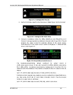
3. Set the Full-Scale value from the front panel screen (Refer Figure 5-4) for
selected channel.
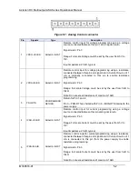
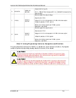
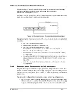
4. Connect a resistance across the VPRG_ISOUR pin and PRG_RTN pin of the
selected channel analog programming interface connecter (refer Figure 5-9).
This will program output voltage for selected channel of the supply.
The
resistance-programming
default
coefficient
for
output
voltage
is
(100% rated output voltage) / 10
kΩ, with input at Pin 2 (VPRG_ISOUR) and return to
Pin 3 (PRG_RTN). An internal current source,
factory-set at 1 mA. This produces a
transfer function for output voltage, as follows:
Vout = R * (100% rated output voltage) / 10
kΩ), with R in kilo ohms.
Full Scale voltage programming resistance can be modified from default 5kOhms to
any other value, from 5
kΩ to 10kΩ, refer to Section 3.4.9.3. Then the transfer function
for output voltage, as follows:
Vout = R * (100% rated output voltage) / FSC kΩ), with R in kilo ohms.
Figure 5-9: Remote Voltage Programming Using Resistance
5.4.2
Remote Voltage Programming by Voltage Source
Programs the output voltage of the supply by external voltage reference source. Refer
Section 3.4.9.3 to configure the power supply to program output voltage by external
reference source using front panel screen or refer programming manual P\N:
M330517-01.
Power supply configurations to program output voltage by voltage source:
1. Set the Voltage Reference Mode as external (EXT) from the front panel Voltage
ref mode screen for selected channel; refer Figure 5-8, this allows the supply
output voltage to be programed form external source for selected channel.
2. Set the Voltage Reference Source as voltage from the front Panel (refer to
Figure 5-3) for selected channel. With the settings made, power supply output
voltage could be programed using only by external voltage source.

