background image

5.0 Display Panel

502783  issue 5

5.0 Display Panel

9

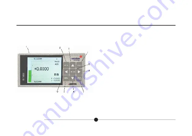
5.1 Layout of Front Panel


1    Liquid Crystal Operator Colour Display


2    Return to Setup Menu


3    Scroll Up (Moves cursor around screen), Apply Preset (ABS/PRE)


4    Print Option


5    Enter 


6    Scroll Right (select option)    


7    Track,  Peak+,  Peak-, Diff


8    Scroll Down (Moves cursor around screen)


9    Zero  (ABS/TARE)


10  Scroll Left (select option)

Summary of Contents for Solarton Metrology Oribt SI3500

Page 1: ...The SI3500 is a member of the SI3000 Readout Family All members of the family are marked SI3000 on the front panel This manual is specifically for the SI3500 Model with Digital Orbit Interface user an...

Page 2: ...4 Orbit Connectors 45 9 0 Technical Specifications 46 Return Of Goods Solartron Sales Offices Section Title Page 1 0 Index 1 2 0 Safety Summary 2 Warnings and Cautions 2 3 0 Service and Repair 4 4 0...

Page 3: ...pment or other property Symbols in this Manual This symbol indicates where applicable cautionary or other information is to be found Service Safety This equipment has been designed and tested to meet...

Page 4: ...ipment without the covers and panels fitted There are no internal adjustments required during commissioning of the equipment Grounding the Equipment The unit is supplied by 24V DC and therefore does n...

Page 5: ...arts This equipment must be returned to your Solartron dealer for any service and repair The SI3500 is designed to be maintenance free Contact with solvents should be avoided Any attempt to dismantle...

Page 6: ...502783 issue 5 4 0 Bench Mounted or Installed into a Panel 4 1 Bench Mounted with associated Solartron Orbit Digital Probes and power supply 4 0 Bench Mounted or Installed into a Panel 5...

Page 7: ...not over tighten the screws as this may damage the case of the instrument WARNING On installing or removing the SI3500 you must be aware of any hazardous equipment or materials in the vicinity Make su...

Page 8: ...502783 issue 5 4 0 Bench Mounted or Installed into a Panel cont 4 3 Panel Dimensions 4 0 Bench Mounted or Installed into a Panel cont 7...

Page 9: ...502783 issue 5 4 0 Bench Mounted or Installed into a Panel cont 4 4 Assembly Dimensions 4 0 Bench Mounted or Installed into a Panel cont 8...

Page 10: ...iquid Crystal Operator Colour Display 2 Return to Setup Menu 3 Scroll Up Moves cursor around screen Apply Preset ABS PRE 4 Print Option 5 Enter 6 Scroll Right select option 7 Track Peak Peak Diff 8 Sc...

Page 11: ...issue 5 5 0 Display Panel cont 10 5 2 Layout of Rear Panel 11 Screen Earth 12 Input Output Connection 13 RS232 Communications 14 24V DC ON OFF Switch 15 24V DC Supply 16 Orbit Connection 17 Orbit Con...

Page 12: ...n dual measurement mode the sensor information A and B only it is not possible to display any combinational information in dual display mode Note B A a limited to 2 5 deg Limits Upper and lower limits...

Page 13: ...he displayed reading only does not change the analogue outputs Enable preset from the preset menu and activate with the up arrow key In dual display mode it is possible to set the preset and zero to a...

Page 14: ...rating Screen 502783 issue 5 6 0 Operating Screen 13 Display seen directly after powering up Note This screen will vary depending on the Operator Screen displayed prior to powering down Press MENU go...

Page 15: ...s for the Se rial RS232 Port Utilities 6 8 Restore Factory Default Settings Exit Menu 6 9 Shows Operator Screen Measurement 6 3 Selects Measurement type A B A B etc Measurement Mode Track Peak Peak Di...

Page 16: ...to return to the Operator Screen With cursor over NEXT MENU Press ENTER for next sub Menu With cursor over EXIT MENU Press ENTER to return to Setup Menu All Solartron Orbit Probes have a unique ID 15...

Page 17: ...ting Screen cont 502783 issue 5 6 0 Operating Screen cont 6 2 1 Probe Type Channel A Use to move the cursor around the screen Use to select options 16 Orbit see 6 2 Press ENTER see 6 2 2 Probes menu C...

Page 18: ...turn to the Operator Screen With cursor over NEXT MENU Press ENTER for next sub Menu With cursor over EXIT MENU Press ENTER to return to Setup Menu With cursor over Back Press ENTER to return to Chann...

Page 19: ...02783 issue 5 6 0 Operating Screen cont 6 2 2 1 Probe type Channel B Use to move the cursor around the screen Use to select options 18 Press ENTER see 6 1 Back to Setup Menu Press ENTER see 6 2 Back t...

Page 20: ...en cont 6 3 Measurement Menu Page 1 Use to move the cursor around the screen Use to select options 19 Orbit see 6 2 Distance B A B A B 2 A B A B 2 B A a Angle limited to 5 deg PEAK PEAK or Diff see 6...

Page 21: ...elect options 20 Measure Type B A B A B 2 A B A B 2 B A a Shows on Operator Screen in mm inch for distance Shows on Operator Screen in rad deg for angle Measure Mode Track Peak Peak Diff Auto Manual A...

Page 22: ...en Use to select options 21 Measure Type B A B A B 2 A B A B 2 B A a Shows on Operator Screen in mm inch for distance Shows on Operator Screen in rad deg for angle Measure Mode Track Peak Peak Diff Au...

Page 23: ...splayed Top xx mm inch Bottom xx mm inch Centrally Tracks the measurements within limits in green turning to red when outside the limits flashes OVER UNDER when outside the Measurement range Unipolar...

Page 24: ...ks the measurements within limits in green turning to red when outside the limits flashes OVER UNDER when outside the Measurement range Unipolar selected Measurement range displayed Top xx rad deg Bot...

Page 25: ...around the screen Use to select options 24 Press ENTER to Edit parameter To move cursor To increment decrement numbers To change Press ENTER to Exit Mode 3 types of limits can be displayed A B and Com...

Page 26: ...rating Screen cont 6 5 Input Output Menu Use to move the cursor around the screen Use to select options 25 Active High Active High 0 to 10V 5 to 5V 10 to 10V 4 20mA 0 to 10V 5 to 5V 10 to 10V 4 20mA C...

Page 27: ...nt 502783 issue 5 6 0 Operating Screen cont 6 6 Serial Port Menu Use to move the cursor around the screen Use to select options 26 2400 4800 9600 19200 38400 7 8 0 5 1 5 2 odd even C55 Press ENTER see...

Page 28: ...en Offsets bar or Switches Bar Auto Range On Off Sets places after Decimal Point This needs to be set separately for CHA CHB Computed Measurement A B A B etc 0 5 10 15 20 25 30 35 40 45 50 55 60 65 70...

Page 29: ...7 Display Menu Screen 2 Use to move the cursor around the screen Use to select options Use On Off Press ENTER to Edit number To move cursor To increment decrement number To change Press ENTER to Exit...

Page 30: ...6 0 Operating Screen cont 6 8 Utilities Menu Use to move the cursor around the screen Use to select options 29 Press ENTER To Restore Factory Default Settings see 6 8 3 Set Password Press ENTER see 6...

Page 31: ...e to move the cursor around the screen Use to select options Keys to turn On Off Default set to 1234 Use ENTER and keys to change Press ENTER to confirm Lock Menu Lock ALL Note If Lock ALL is applied...

Page 32: ...02783 issue 5 6 0 Operating Screen cont 31 6 8 2 Password Entry Note Only seen if password enabled Use to move the cursor around the screen Use to select options Press to select parameter Press ENTER...

Page 33: ...cont 502783 issue 5 6 0 Operating Screen cont 6 8 3 Utilities Menu Factory Default Restore The following is displayed for 3 seconds the unit automatically defaults to factory setting and returns to th...

Page 34: ...utside the set limits Pressing ENTER resets PEAK Measures within the set limits displaying green turning red when outside the set limits Pressing ENTER resets DIFF measures Peak Peak measures within t...

Page 35: ...creen cont 502783 issue 5 6 0 Operating Screen cont 34 Press Zero to TARE Press to apply Preset see 6 7 or ABS Absolute Transducer X measurement Transducer Y measurement To select channel for Zero etc...

Page 36: ...5 6 0 Operating Screen cont 35 Use to select Standard Start on Discrete Input or Trigger on Discreet Input Press ENTER to edit number To Move Count To Increment Number Press ENTER to Exit mode 6 11 Lo...

Page 37: ...6 0 Operating Screen cont 502783 issue 5 6 0 Operating Screen cont 36 6 12 Logging Menu Page 2 Use to move to option Press ENTER to Select option...

Page 38: ...enu Extended Print P 1 Print in SI3500 Format Get Detail E 2 Return Details about the SI3500 ABS or TARE Measurement Type Unit of Measure Limit Values Set Unit S 11 Set Various SI3500 Settings Limits...

Page 39: ...Extended Print Current Measurement 3 P 0 Channel A 3 P 1 Channel B 3 P 2 GetDetail Get Abs or Tare 4 E A 0 Get Measurement Mode 4 E M 0 Get Unit of Measure 4 E U 0 Get Current Mode LL 4 E L 0 Get Cur...

Page 40: ...uted UL 13 S L C U 1 2 3 4 sp sp sp Set Computed LL 13 S L C L 0 7 8 9 sp sp sp Set Measurement Type A 13 S M 0 sp sp sp sp sp sp sp sp sp B 13 S M 1 sp sp sp sp sp sp sp sp sp A B 13 S M 2 sp sp sp s...

Page 41: ...P L O sp sp sp Logic Inputs Active High 13 S I I N P H I sp sp sp Logic Outputs Active Low 13 S I O U T L O sp sp sp Logic Outputs Active High 13 S I O U T H I sp sp sp Notify Notify Probe Channel A 1...

Page 42: ...Example 0 00017mm 0 0 0 0 1 7 m m n r 0 0017mm 0 0 0 1 7 m m n r 0 017mm 0 0 1 7 m m n r NORMAL 0 1 2 3 4 5 6 7 8 9 10 11 12 13 14 15 16 17 18 19 20 21 22 23 Format Sign Reading right aligned DP set b...

Page 43: ...lable via remote RS232 commands P0 or P1 or P2 It is not selected just requested XY mode 0 1 2 3 4 5 6 7 8 9 10 11 12 13 14 15 16 17 18 19 20 21 22 23 24 25 26 27 28 29 30 31 32 33 34 35 36 37 38 39 4...

Page 44: ...Print key Isolated I P 18 Reset key Isolated I P 6 Peak key Isolated I P 19 Log Control 7 Preset Enable 20 Isolated I P Common 8 Not Used 21 Not Used 9 Not Used 22 Not Used 10 Not Used 23 CH1 Analogue...

Page 45: ...URATION 1 Not Used 2 RS232 Tx 3 RS232 Rx 4 Not Used 5 RS232 GND 6 Not Used 7 Not Used 8 Not Used 9 Not Used 8 3 POWER CONNECTOR Mounted on rear panel 2 5 mm Chassis Mounted DC skt PIN DESCRIPTION DETA...

Page 46: ...cont 8 4 ORBIT Connectors 2 off 9 way D Type Sockets in recess under rear panel ORBIT CONNECTION From Orbit Adapter PIN DESCRIPTION 1 Not Used 2 RS485 A 3 RS485 B 4 Not Used 5 0V 6 5V 7 5V 8 Not Used...

Page 47: ...imum at 24V DC Universal 100 240V AC Input 24V DC PSU supplied with unit MECHANICAL Weight 1 1kg excluding transducers Dimensions See drawing ELECTRICAL CONNECTIONS Rear Panel DC Power 2 5mm DC Socket...

Reviews: