Instructions
4
Data Entry Footswitch Operation Manual
Instructions
INSTALLATION & SETUP
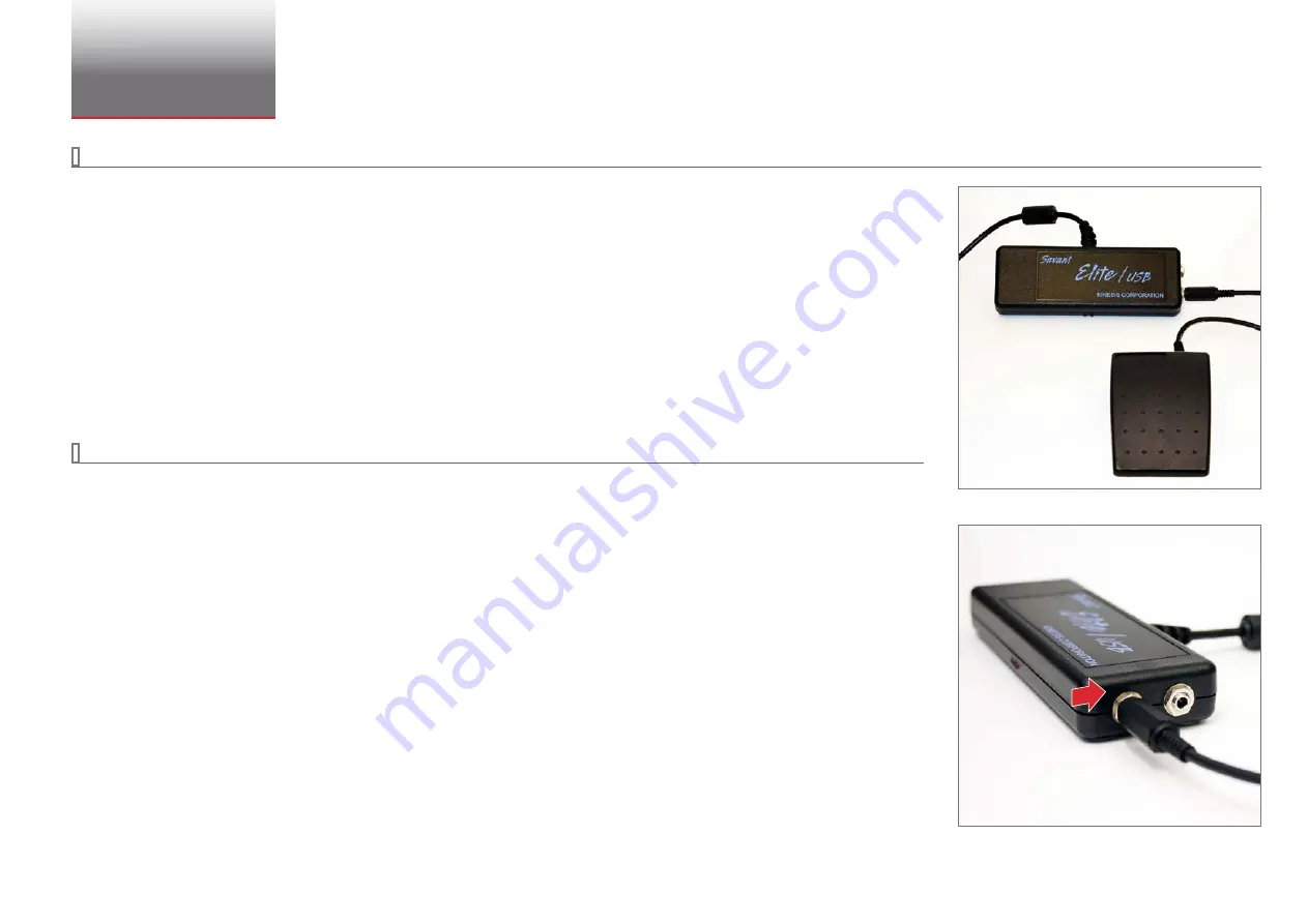
The foot switch comes in two pieces. The Control Module, which has an attached USB cable and two 1/8" sockets, and the Foot Switch, which has an
attached cable ending in an 1/8" plug.
Note:
When connecting the Foot Switch to a computer for the first time, it is best to connect it after your computer has booted up and is logged in. This
will enable the “new device detected” message to be displayed, which usually completes within less than a minute. The process will be repeated
if you plug the device into a different USB port, even on the same computer.
1
Connect the control module to any available USB port.
Note:
No drivers are required for operation. The foot switch may be connected before or after the installation of your Crystal Engineering software.
2
Plug the foot switch into the left socket on the control module, as shown in the photo, and place the foot pedal in a convenient location.
Note:
If using the Elite 2 foot switch, plug the cable into the right socket.
OPERATION
Pressing the foot switch should have no effect except as appropriate within your Crystal application, and should not have any affect on other Windows
applications. See your software user’s manual for more information.
Control Module and Foot Switch
Foot Switch cable plugged into the left socket


