5555553COM
CoCeCrooC 5 Crawer CreCCer
25
ameriwoodhome.com
*raw edges are shaded
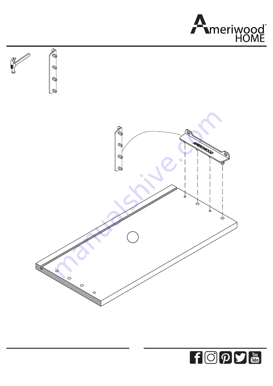
Step 20
7
x6
TPB
00
41
x6 Set
Insert the drawer bracket to the six set of
drawer side left(7).
Page 1: ...items on lower shelves or drawers WARNING Co Not Return ThiC Product Contact our customer service team for help CaCC 1 800 489 3351 toll free Monday Friday 9am 5pm CST ViCit www ameriwoodhome com Fol...
Page 2: ...are labeled with a R right and L left for proper placement Make sure to always face the point on the top of the Cam Lock towards the outer edge Use all the nails provided for the back panel and spread...
Page 3: ...proper order Separate and count all your parts and hardware Give yourself enough room for the assembly process Have the following tools Flat Head Screwdriver 2 Phillips Head Screwdriver and Hammer Cau...
Page 4: ...5969503030 SIDE PANEL RIGHT x1 T5969502040 PARTITION PANEL x6 T5969502050 DRAWER FRONT x6 T5969502060 DRAWER BACK x6 T5969502070 DRAWER SIDE LEFT x6 T5969502080 DRAWER SIDE RIGHT x1 T5969502090 SIDE R...
Page 5: ...Board Ident if icat ion Not actual size 5 ameriwoodhome com x1 T5969502150 BACK PANEL x6 T5969502160 DRAWER BOTTOM x1 T5969502130 KICK PANEL x1 T5969502140 BOTTOM PANEL 13 14 16 15...
Page 6: ...CB 4 X 12 x12 TPB0040 PH M4 X 20 x56 TPB0005 DOWEL 6 X 30 x28 TPB0010 NAIL Not Actual Size x6 TPB0042 PULL HANDLE 96MM x6 Set TPB0036 DRAWER SLIDE 300 MML x2 TPB0043 DOUBLE END BOLT 64MM x12 TPB0041 D...
Page 7: ...ded Step 1 2 FRONT BACK SCREW HOLE POSITION x2 TPB0002 x4 TPB0005 x12 TPB0007 x2 TPB0001 x3 TPB0036 x3 Proper orientation of CAM LOCK Tip Assembly Quick Insert two cam lock two screw cam bolt and four...
Page 8: ...raw edges are shaded Step 2 x2 TPB0002 x4 TPB0005 4 x24 TPB0007 LEFT SURFACE x3 x3 RIGHT SURFACE FRONT BACK FRONT BACK SCREW HOLE POSITION SCREW HOLE POSITION x3 TPB0036 Proper orientation of CAM LOCK...
Page 9: ...ded Step 3 3 FRONT BACK SCREW HOLE POSITION x2 TPB0002 x4 TPB0005 x12 TPB0007 x2 TPB0001 x3 TPB0036 x3 Proper orientation of CAM LOCK Tip Assembly Quick Insert two cam lock two screw cam bolt and four...
Page 10: ...10 ameriwoodhome com raw edges are shaded Step 4 11 x4 TPB0002 x4 TPB0005 x2 Set Proper orientation of CAM LOCK Tip Assembly Quick Insert two cam lock and two dowel into two set of panel as shown...
Page 11: ...11 ameriwoodhome com raw edges are shaded Step 5 12 x4 TPB0002 x4 TPB0005 x2 Set Proper orientation of CAM LOCK Tip Assembly Quick Insert two cam lock and two dowel into two set of panel as shown...
Page 12: ...12 ameriwoodhome com raw edges are shaded Step 6 11 2 11 Attach two left brace 11 to the left panel 2 as shown...
Page 13: ...13 ameriwoodhome com raw edges are shaded Step 7 4 2 11 11 x2 TPB0043 Attach partition panel 4 to the left brace as shown...
Page 14: ...14 ameriwoodhome com raw edges are shaded Step 8 4 12 12 11 11 2 Attach two right brace 12 to the partition panel 4 as shown...
Page 15: ...15 ameriwoodhome com raw edges are shaded Step 9 2 11 11 4 12 12 3 Attach right panel 3 to the right brace 12 as shown...
Page 16: ...16 ameriwoodhome com raw edges are shaded Step 10 9 x2 TPB0005 Insert two dowel into side rail left as shown...
Page 17: ...17 ameriwoodhome com raw edges are shaded Step 11 10 x2 TPB0005 Insert two dowel into side rail right as shown...
Page 18: ...18 ameriwoodhome com raw edges are shaded Step 12 13 x8 TPB0005 Insert eight dowel into kick panel as shown...
Page 19: ...19 ameriwoodhome com raw edges are shaded Step 13 13 9 Attach side rail left 8 to the kick panel 13 as shown...
Page 20: ...20 ameriwoodhome com raw edges are shaded Step 14 10 13 9 Attach side rail right 10 to the kick panel 13 as shown...
Page 21: ...21 ameriwoodhome com raw edges are shaded Step 15 10 9 14 13 x8 TPB0038 Laminated Face Attach bottom panel 14 to the components from step 14 as shown...
Page 22: ...22 ameriwoodhome com raw edges are shaded x6 TPB0001 Step 16 x1 set TPB0017 1 kit into the top panel as shown...
Page 23: ...23 ameriwoodhome com raw edges are shaded Step 17 x6 TPB0038 2 11 4 12 14 9 10 13 3 11 12 Attach the components from step 15 to the components from step 9 as shown...
Page 24: ...24 ameriwoodhome com raw edges are shaded Step 18 1 11 11 12 12 14 4 3 2 Attach the components from step 16 to the components from step 17 as shown...
Page 25: ...A0010 Attached the back panel as shown nailing straight into the raw edges Assure that the unit is square Distance from corner to corner must be equal as shown IMPORTANT THE BACK PANEL IS A STRUCTURAL...
Page 26: ...26 ameriwoodhome com raw edges are shaded Step 20 7 x6 TPB0041 x6 Set Insert the drawer bracket to the six set of drawer side left 7...
Page 27: ...27 ameriwoodhome com raw edges are shaded Step 21 8 x6 TPB0041 x6 Set Insert the drawer bracket to the six set of drawer side right 8...
Page 28: ...28 ameriwoodhome com raw edges are shaded Step 22 6 x24 TPB0005 x6 Set Insert four dowel to the six set of drawer box back 6...
Page 29: ...29 ameriwoodhome com raw edges are shaded Step 23 8 6 x12 TPB0038 x6 Set Attach the components from step 21 to the components from step 22 as shown...
Page 30: ...30 ameriwoodhome com raw edges are shaded Step 24 7 8 x12 TPB0038 6 x6 Set Attach the components from step 20 to the components from step 23 as shown...
Page 31: ...31 ameriwoodhome com raw edges are shaded Step 25 6 7 8 5 16 x24 TPB0039 x6 Set Insert the drawer bottom 16 in grooving line Attach the drawer front 5 to the components from step 24 as shown...
Page 32: ...32 ameriwoodhome com raw edges are shaded Step 26 6 7 8 5 16 x12 TPB0040 x6 TPB0042 x6 Set Attach the handle to the components from step 25 as shown...
Page 33: ...33 ameriwoodhome com raw edges are shaded Step 27 x36 TPB0007 x6 Set TPB0036 SCREW POSITION LEFT RIGHT 6 8 16 x6 Set Attach the drawer slide to the bottom of components from step 26 as shown...
Page 34: ...njuries can occur Place heaviest items in the lowest drawers do not set TVs or other heavy objects on the top of this product Never allow children to climb or hang on drawers door or shelves Never ope...
Page 35: ...meriwoodhome com raw edges are shaded Step 29 1 2 5 5 5 5 5 Notice the drawer bracket holes are slotted Drawer fronts can be adjusted by loosening screws making needed adjustments and retightening scr...
Page 36: ...d for use with a television 1 This certificate applies to the Dorel Home Furnishings Inc product identified by this instruction manual 2 This certificate applies to compliance of this product with the...
Page 37: ...deaCC and diCcount codeC QuicC and eaCy repCacement part Cervice To regiCter your product viCit ViCit your CocaC retaiCer C weCCite rate your purchaCed product and Ceave uC Come feedCacC We wouCd CiC...
Page 38: ...el punto locaizado en la parte superior de bloqueador de leva este volteadohacia borde exterior todos los clavos para el panel de atras y distribuirlos por igual El panel de atras debe para asegurars...
Page 39: ...ecte los componentes del paso 16 a los componentes del paso 17 como se muestra Fije el panel inferior 14 a los componentes del paso 14 como se muestra Fije el riel lateral derecho 10 al panel de chave...
Page 40: ...TRE FIX AU MUR POUR AIDER PR VENIR LE BASCULEMENT SUIVRE CES INSTRUCTIONS POUR INSTALLER LE SUPPORT DE S CURIT ANTI BASCULEMENT FOURNI AVEC CE PRODUIT ATTENTION BCeCCureC par craCement graveC ou morte...
Page 41: ...upport de s curit dans la planche Conduisez la vis travers le support de s curit dans le montant du mur Serrer la vis qui n a pas t Localisez votre meuble o d sir contre un mur et marquer le mur trave...
Page 42: ...res sont marqu es d un R droit et d un L gauche pour un bon placement Assurez vous toujours de faire face la pointe situ sur le haut de la Serrure de Came vers le bord ext rieur tous les clous fourni...
Page 43: ...Connecter les composants de l tape 16 l tape 17 composants comme indiqu Fixer le panneau inf rieur 14 pour les composants de l tape 14 comme illustr R glez le rail lat ral droit 10 sur les broches du...
Page 44: ...33 Page 34 Page 29 Page 30 CHARGES MAXIMALES Ce meuble a t con u pour supporter les charges maximales indiqu es En exc dant ces limites de charge le meuble pourrait devenir instable et ou causer des b...
Page 45: ...trous sont fendus support du tiroir fronts de tiroir peut tre r gl en desserrant les boulons les ajustements n cessaires et des vis de fixation Enregistrez votre produit pour recevoir les l ments sui...