12
Page 1: ...P N 98 0034 Rev B 5NOV09 VARIABLE SPEED PUMP SYSTEM OPERATION MAINTENANCE MANUAL Manufactured With Pride In The USA www ameriwater com 800 535 5585 AmeriWater 3345 Stop 8 Rd Dayton OH 45414...
Page 2: ...OR OVERLOAD APPLICATION SWITCH SETTING AquaBoost II WIRING DIAGRAM 9 DIAGRAMS TYPICAL MOTOR NAMEPLATE SHOWING SERVICE FACTOR AMPS SF AMPS LABELS FOUND ON THE CONTROLLER ACCESS COVER 10 TROUBLESHOOTING...
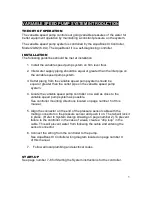
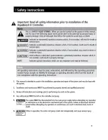
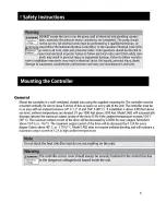
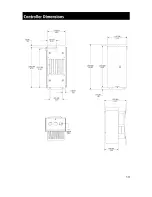
Page 3: ...the outlet pipe on the variable speed pump system 4 Locate the variable speed pump controller on a wall as close to the variable speed pump system as possible See controller mounting directions locate...
Page 4: ...2...
Page 5: ...3...
Page 6: ...4...
Page 7: ...5...
Page 8: ...6...
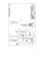
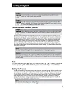
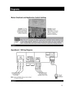
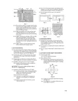
Page 9: ...7 Note The Motor Overload Switch is set when the Variable Speed Pump System is built It should be checked periodically The DIP Switch Setting has been set at 1011 for a 5 8 AMP Motor...
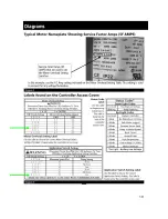
Page 10: ...indicates that the pump is running A Blinking or Solid Red Light Indicates a problem with the controller Refer to the access cover side panel or Diagram 6 for Status Codes See Troubleshooting Section...
Page 11: ...9...
Page 12: ...10...
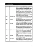
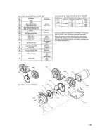
Page 13: ...11 Note See the Pump s Trouble Shooting Chart on page 18 in reference to the Controller s Trouble Shooting Indicator Code Status Description...
Page 14: ...12...
Page 15: ...13...
Page 16: ...14...
Page 17: ...15...
Page 18: ...16...
Page 19: ...17...
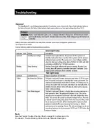
Page 20: ...18 NOTE See the AquaBoost Controller s Trouble Shooting Indicator Code Status Description on pages 11 12 in reference to the Pump s Trouble Shooting Chart...
Page 21: ...19...
Page 22: ...20...
Page 23: ...to cause cancer birth defects or other reproductive harm One such chemical is Vinyl Chloride a compound used to produce Polyvinyl Chloride PVC The AmeriWater system you have purchased may contain PVC...