background image

STRATOS VERTICAL PLATFORM LIFTS:


Install Manual

04DEC2020  |  630-00147 REV A

21

INSTALLATION

STRATOS: SECTION 4

OPERATOR FAMILIARIZATION 

Upon completion of the installation, it is imperative 

to review all contents of the Owner’s Manual with 

the customer and provide a thorough demonstration 

and familiarization of the lift.  

In residential applications, this is should be 

conducted with the end-user and any or all of the 

following: homeowner, family members, caregiver 

etc. You should not leave until the end-user or 

primary lift operator has demonstrated they can use 

the lift properly.  

In commercial applications this would take place 

with any or all of the following: the property owner, 

facilities manager, or any personnel who may 

oversee the unit’s use or control its access.  

PROVIDE OVERVIEW


Review all warnings


Describe how the lift works and familiarize  


with key components


Pre-use inspection

DESCRIBE AND DEMONSTRATE PROPER USE AND 

EACH KEY


Call/Send


Entrance and positioning


Door/Gate interlocks and safety pan  


Status lights and color key


Ascend/Descend


Use of handrail 

(if equipped)


Emergency lowering

REVIEW CARE AND MAINTENANCE


Keys


Maintenance items


Inspection items


Rust prevention

Be sure to leave them with the Owner’s Manual 

and that your contact information has been written 

into it as well as on the labels in the cab and on 

the tower. Have them complete the Warranty 

Registration while you are there.

Summary of Contents for STRATOS

Page 1: ...04DEC2020 630 00147 REV A VERTICAL PLATFORM LIFT INSTALLATION MANUAL STRATOS ...

Page 2: ......

Page 3: ...TION 12 No Hoistway No Floor Penetration 12 Platform Connection 12 Installing the Platform Control Guard Panel 13 Installing a Platform Gate If Equipped 14 Installing the Platform Front Guard Panel 14 Installing the Auto Folding Ramp 14 Installing the Top Landing Gate 15 Fascia Panel Installation 16 Setting the Upper Limit Switch 16 Doors Gates by Others 17 Call Stations 17 Final Positioning and A...

Page 4: ...ions that jeopardize the technician s safety or ability to complete the installation in a safe manner Tents canopies or other outdoor provisions that help protect the work area from weather or other safety concerns are recommended when conditions warrant If you do not understand any portion of the installation or operation procedures please consult Ameriglide s Technical Service Department at 866 ...

Page 5: ... the particular lift model and configuration CODE STATEMENT The Ameriglide Stratos lift has been designed to meet ASME A18 1 Safety Standard for Platform Lifts and Stairway Chairlifts under section 2 or section 5 and has been certified to CAN CSA B44 1 ASME A17 5 Elevator and Escalator Electrical Equipment Code requirements for Vertical Platform lifts may vary depending on location It is the insta...

Page 6: ...ust comply with 2 1 1 and with the building code NOTE There are 3 different sections of rules for a commercial application 2 1 1 Runway Enclosure Provided 2 1 2 Partial Runway Enclosure Provided 2 1 3 Runway Enclosure Not Provided code has a height restriction under rule 2 7 ASME A18 1 SECTION 5 PRIVATE RESIDENCE VERTICAL PLATFORM LIFTS Section 5 applies to vertical platform lifts installed in or ...

Page 7: ...N STRATOS SECTION 2 KEY VERTICAL PLATFORM LIFT ELEMENTS 1 Top Cap 2 Lift Status Indicator Lights 3 Data Serial Tag 4 Platform 5 Platform Side Panel 6 Grab Rail if supplied 7 Platform Controls 8 Platform Safety Pan 9 Platform Folding Ramp Platform Fixed Ramp 10 Tower 1 2 10 3 7 5 6 8 4 9 ...

Page 8: ...rew 4 Batteries if supplied 5 Battery Charger and assembly tray if supplied not shown 6 Inverter if supplied 7 Control Electronics Assembly 8 Upper Lower Lower Final Limit Switches 9 Tower Frame 10 Tower Legs 11 Wire Channel 12 Over Speed Safety Assembly 13 Motor Contactors 14 Carriage 15 Trailing Cable 16 Cable Tensioning Pulley 17 Main Power Supply Hook up 1 13 2 7 9 8 15 11 6 4 17 3 14 10 12 16...

Page 9: ...quare Level Multimeter Wire Cutters Wire Puller Stripper Crimping Tool Hammer Drill 3 8 Wrench Set 7 16 1 2 9 16 3 4 Allen Wrench 1 8 3 16 5 16 Torx Wrench T20 No 1 Phillips Head Screwdriver No 2 Flat Head Screwdriver No 2 Phillips Head Screwdriver Marking Implement 3 8 Nut Driver Bit with 1 5 min reach or 3 8 socket extension and ratchet Concrete Drill Bits Temporary Power Means Precision Screwdr...

Page 10: ...The 4 VPL is shipped standing up shrink wrapped to a pallet The pallet dimensions are 48 x 48 x 83 Units are screwed into the pallet installers will require a 3 4 wrench socket to remove screws A lift gate is unable to be used on models 6 or taller which are shipped laying back A pallet jack or forklift can be used to set into place Note Must have a loading dock pick up the VPL at the shipping ter...

Page 11: ...uld be taken not to scratch or damage panels when removing carrying and reinstalling them Special care must be taken to protect any landscaping or flooring surfaces that might be damaged by the uses of material handling equipment HOIST WAY SHAFT If a shaft is needed and is being built by someone other than the installer it s important to provide detail drawings and specifications for the shaft way...

Page 12: ...uld only be lifted by the rectangular tubes below the top plate PLATFORM CONNECTION 1 Remove and discard the temporary bolt and nut 9 16 hex that secures the tensioning pulley to the carriage for shipping This bolt is indicated with a red tag Suspend the pulley assembly behind the carriage See Figure 4 2 Pulley Assembly Temporary Shipping Bolt Figure 4 2 NOTE Be sure that the pulley assembly is su...

Page 13: ...he service button on the control electronics board All four 4 status indicator LED s will flash green to show that Service Mode is active The unit will remain in Service Mode for ten 10 minutes Press the service button again if needed 8 Use the platform control box to move the carriage up or down to align the platform and carriage mounting holes 9 Install the four 4 1 2 bolts using the low profile...

Page 14: ...LING THE PLATFORM FRONT GUARD PANEL Insert the front guard panel posts into the pockets on the platform with the smooth side facing the inside of the platform Fasten in place with four 4 1 4 20 x 2 bolts If an auto fold ramp option is being installed the ramp brackets must be installed with this hardware INSTALLING THE AUTO FOLDING RAMP 1 Attach the two ramp pivot tabs to the lower landing sides o...

Page 15: ... for type and mounting requirements After wiring is completed the wiring harness must be plugged into the appropriate receptacle on the controller Wiring Connections Call Send Lift Harness Wire Blue Blue Up White White Communication Red Red Down NOTICE NOTE If the call send switch is installed in the gate the wires are routed between the gate and to the top of the tower If the call send is located...

Page 16: ... FASCIA PANEL INSTALLATION The fascia panel sections are available in 53 and 24 heights and 41 and 49 widths Custom fascia panel heights can be special ordered Fascia panels must provide a smooth surface for the platform edge to run against to prevent any shear or obstruction hazards They must be fastened beneath the opening and adjacent to each other with no overlapping or gaps between them The u...

Page 17: ... 4 10 Back Cover Front Cover 4 Cover Screws Label Plate Figure 4 10 2 Remove four 4 cover screws and front cover from back cover 3 Determine mounting and wiring method Verify applicable code requirements 4 If using the back cover for a wall mount setup cut out the desired knock out for wire routing There are four 4 knockouts on the back cover Two 2 on the back surface one 1 on the top and one 1 on...

Page 18: ...models must have the lift tower anchored at two 2 levels into a solid surface at or above the top two 2 tower cross braces This is to ensure running clearances remain constant There are two options for anchoring the top of the tower See Figure 4 13 Anchor Anchor 8 10 12 14 Anchor Anchor Figure 4 13 The 1st option is to use the optional tower brace that attaches to the sides for the tower There are...

Page 19: ...the pulley is hanging in the tower without hitting any obstacles during platform travel Verify that the manual lowering wrench and socket are in place and secured on the top plate with wing nuts Verify that the E Stop is functional and all 4 LED lights are solid red with no lift movement Verify the screws securing the tower skins have a plastic washer and are tight Reset the board Enter service mo...

Page 20: ...tons control UP and DOWN travel Key switch if equipped OFF on Call Stations stops and prevents travel from Call Station Safety pan switches depressed prevent DOWN travel and allow UP travel check several locations Indicator lights one 1 and 2 are flashing AMBER Pit switch if equipped prevents UP and DOWN travel Indicator lights 1 2 and 3 are solid RED PERMANENT POWER INSTALLATION Permanent power c...

Page 21: ...s this would take place with any or all of the following the property owner facilities manager or any personnel who may oversee the unit s use or control its access PROVIDE OVERVIEW Review all warnings Describe how the lift works and familiarize with key components Pre use inspection DESCRIBE AND DEMONSTRATE PROPER USE AND EACH KEY Call Send Entrance and positioning Door Gate interlocks and safety...

Page 22: ...x4 beneath platform base when connecting to carriage INSTALL LANDING GATE Screw to Landing Pre run Wiring INSTALL FASCIA PANEL Attach to Open Areas Under Gate Ensure Smooth Flush No Gaps Protrusions etc TIP Use flat screw heads to avoid protrusions FINAL POSITIONING ANCHORING Level and Perpendicular Anchor Tower Legs Anchor Tower to Structure Fixed Ramp Securement VERIFY CLEARANCES Platform openin...

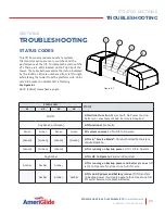
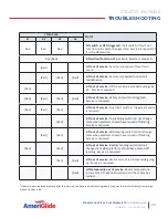
Page 23: ...hing light STATUS LED STATUS 1 2 3 4 All OFF Lift will not function Major Fault No Power and no battery or Low Power Mode Service is Required Any Green or Green Lift functional No faults Green Green Green Green All systems normal Lift is OK to Operate Green Green Green Green Lift is in Service Mode Only Authorized Technicians should Operate Green Green Green Lift is running on backup power Lift is...

Page 24: ...r Motor is drawing too much current Platform will only go down Service is required Amber Amber Safety pan has been triggered Platform will only go up Amber Float switch has been triggered Platform will only go up Service will be required to ensure safe operation Alarm will turn into a Major Fault after 25 full cycles or two 2 weeks time after flood event Amber Amber Motor temperature monitoring lo...

Page 25: ...t out of service Final limit switch is triggered Service is required Red Lift out of service Top landing switch did not change state when platform should have moved off landing Service is required Red Red Lift out of service Mid landing switch did not change state when platform should have moved off landing Service is required Red Red Lift out of service Bottom landing switch did not change state ...

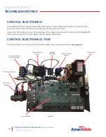
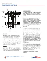
Page 26: ... If the Indicator LEDs do not provide enough information to fully troubleshoot a potential issue it may be necessary to access the control electronics below the top cap of the tower Access the control electronics by loosening seven 7 top cap screws lifting the top cap and unplugging the indicator board cable from control board Set top cap assembly aside CONTROL ELECTRONICS TRAY The Control Electro...

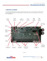
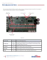
Page 27: ...ts on the Control Board See Figure 6 3 Figure 6 3 Indicator Board Connector Alarm Connector 3A Circuit Breaker Screw Terminal Motor Thermocouple Connector Brake Connector Down Contactor Connector Up Contactor Connector Trailing Cable Connector Gate and Call Station Screw Terminals Landing Switch Connectors Board Programming Connector NOT USED 24VAC Input Screw Terminal Inverter Remote Control Conn...

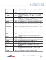
Page 28: ...ator LEDs 26X Green Circuit Status LEDs 3 3V Power LEDs 24V Power LEDs DESCRIPTION COLORS STATUS TROUBLESHOOTING 4X Indicators Green Amber Red These LEDs exactly duplicate the Indicator LEDs on Top Cap If they do not match there could be an issue with cable or Indicator Board Refer to Troubleshooting codes above 3 3V Power Green LED ON indicates processor is getting power 24V Power Green LED ON in...

Page 29: ...D ON indicates the Up button in the Bottom Call Station is being depressed Down Bottom Green LED ON indicates the Down button in the Bottom Call Station is being depressed Bottom Gate Green LED ON indicates the Bottom or Platform Gate Door interlock is closed Bottom Lock Green LED ON indicates the Bottom or Platform Gate Door lock is active Up Mid Green LED ON indicates the Up button in the Mid Ca...

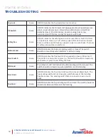
Page 30: ... safety pan switches in platform Bottom Land Green LED ON indicates the Bottom Landing switch is closed The switch should be closed only when platform is at that landing Float Switch Green LED ON indicates the float switch if equipped is closed Minor Fault The platform is only able to move up The switch should be closed only when water is present and lifting the float Mid Land Green If a 3 Stop li...

Page 31: ... brake operation and is recommended to be used in the emergency lowering procedure RESET MOMENTARY SWITCH Pressing the RESET momentary switch will reset the processor and exit Service Mode if board were in that mode Out of Service Mode flag is not cleared by pressing the RESET switch The control board has three 3 momentary switches and three 3 permanent cuttable switches jumpers See Figure 6 5 Fig...

Page 32: ... change based on configuration If needed these jumpers are cut in the factory and should never need to change 3 STOP JUMPER This jumper is cut in the factory on 3 stop lifts The control board will ignore any mid landing circuits when this jumper is intact TG JUMPER UNUSED In the future this jumper will be used on Toe Guard lifts AUX JUMPER UNUSED This jumper could be used for future expansion feat...

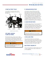
Page 33: ...s engaged after the motor comes to a stop If the platform is taking too long to come to a stop there could be an issue with this resistor or the wiring on it LOAD RESISTORS The load resistors function is to slow the platforms speed in the DOWN direction The resistors are in circuit only when the DOWN contactor is ON and will generate significant heat as they dissipate some of the downward energy T...

Page 34: ...witches between charging and voltage monitoring The battery voltage is monitored continuously any time while on battery power and checked every 4 hours while on AC power A failed Battery Check Relay would result in a Very Low Battery warning INVERTER The inverter is 1500W and converts the 24V from the batteries into a 120 Volt modified sine wave to power the lift The inverter is controlled by the ...

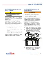
Page 35: ...re to evacuate the occupant EMERGENCY LOWERING PROCEDURE In the event that the lift becomes disabled with passengers on the platform that is not at a landing it may be necessary desirable to manually lower them prior to a technician arriving In that case a manual lowering mechanism is located beneath the top cap of the lift A person other than the lift passenger s will be required to make their wa...

Page 36: ...from drifting with heavy loads Lowering the platform with the brake engaged will require a bit of strength typically the equivalent of being able to lift 20 lb with one arm 6 If the lift has power press and hold the button on the control board labeled BRAKE This will release the brake and make lowering the platform a little easier 7 Rotate the motor shaft clockwise to lower the platform NOTE Do no...

Page 37: ...lt in safety device designed to detect obstructions under the platform and stop platform downward motion If there is an easy to remove obstruction please remove it If for any reason the safety pan does not move as intended please contact your dealer Check and ensure that all labels are intact and legible If any safety or warning labels need to be replaced please contact your dealer Make sure you h...

Page 38: ...egible If any safety or warning labels need to be replaced please contact your dealer Make sure you have a copy of the Owner s Manual A digital copy of the Owner s Manual is available at Ameriglide com Check your key locks and emergency stop button for functionality Check for any rust that may be developing Rust is expected in outdoor applications especially in coastal areas but with proactive mai...

Page 39: ...STRATOS VERTICAL PLATFORM LIFTS Install Manual 04DEC2020 630 00147 REV A 39 NOTES STRATOS ...

Page 40: ...866 378 6648 ameriglide com ...

Reviews: