background image

17

© American Time

Wireless Digital Clocks Owner's Manual

D

e

scr

ip

tio

n

In

st

a

lla

tion

O

p

e

rat

io

n

Co
d

e

 B

lue

M

ai

n

te

n

a

n

ce

A

pp
e

n

d

ix

S

pe
c

ific

at

io

n

s

© American Time

In

st

a

lla

tion

Wireless Digital Clocks Owner's Manual

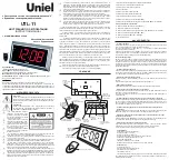
Appendix A: Optional Timer Control Station 

Installation

Figure 1

Pre-drilled hole

WALL

1

8

ETI Control Station

1.  START/STOP/

INCREMENT – Yellow Wire

2.  ETI UP – Brown Wire
3.  ETI DOWN – Blue Wire
4.  SET/RUN – Orange Wire
5.  RESET/ENTER – Grey Wire
6.  12V – Red Wire
7.  PIEZO – Violet Wire
8.  GND – Black Wire

The 

ATSTCS Control Station

 can be mounted to a double gang box, 11/2 

inch deep or deeper. The Control Station can be mounted up to 30 feet away 

from the Digital Clock/Timer. The recommended minimum interconnecting 

field wire size is #22.8 AWG stranded wire.

Ensure that installation conforms to the National Electrical Code and 
local wiring codes.

CAUTION:


Electric Shock Hazard!

 Ensure that 

NO

 electrical power is 

present on any wire before installation.

1.  Pull interconnecting field wires into the double gang box.
2.  Connect field wiring interconnecting the ATSTCS Control 

Station with the Digital Clock/Timer to the appropriate 
wires of the Control Station. See wiring detail below.

3.  Mount the Control Station to the double gang 

box using the machine screws provided. 

4.  Terminate 

S8

S7

S6

S5

S4

S3

S2

S1

BLA

CK

VIOLE

T

RED

GRE

Y

OR

ANGE

BL

UE

BR

OWN

YELL

OW

RESET

ENTER

START/STOP

INCREMENT

SET

RUN

DOWN

CL

OCK

UP

PIEZO

BUZZER

+

K2+

K2-

12VAC/DC TO 30VAC/DC 

POWER ON 

NORMALLY-OPEN 

SWITCHED CIRCUIT 

SUPPLIED FROM CODE BLUE 

UNIT.

CODE BLUE 

UNIT

ATSTCS Wiring DIagram

Summary of Contents for SiteSynq IQ

Page 1: ...Installation and Operation Manual Part H005112 Rev 1 January 2020 Wireless Digital Clocks with Optional Calendar and Elapsed Time Indicator Code Blue...

Page 2: ...nsitive Devices CAUTION This equipment contains electronic devices that are sensitive to static electric charges To guarantee protection for the circuitry of this unit it is required that electrostati...

Page 3: ...tions 5 Description 6 SQA461RSxE Digital Clock Timer 6 ATSTCS Control Station 6 Installation Instructions 7 SQA461RSxE Installation Instructions 7 Operation 8 13 Digital Clock Operation 8 Timer Contro...

Page 4: ...urther information be desired or should particular problems arise which are not covered sufficiently the matter should be referred to the Installer or Original Purchaser listed below INSTALLER INFORMA...

Page 5: ...urrent Digital Clock Timer only 120vac 130mA max 101mA avg Memory Retention on Loss of Line Voltage Up to 10 years from coin cell battery Distance of ATSTCS from Digital Clock Timer 30 ft maximum with...

Page 6: ...ed and reset Both timer modes have a programmable preset value When the timer reaches the preset value a two second audible alarm sounds from the ATSTCS control panel The Code Blue up counting elapsed...

Page 7: ...ched electrical circuit wiring using UL approved wire nuts Route field wiring away from sharp projections and corners 5 Join the wall and clock Molex together 6 Seat the bracket spring in the channel...

Page 8: ...the system controller or by the push buttons on top of the clock see Setting 12 or 24 Hr Mode on pg 11 The ATSTCS timer control station will allow the user to set a 12 or 24 hour mode and time when t...

Page 9: ...will occur at 00 00 00 Set the UP DOWN CLOCK switch to the DOWN position Set the SET RUN switch to the SET position The hours digits will be flashing Using the INCREMENT switch set the desired hours...

Page 10: ...en complete press SET RUN The buttons on the digital clock can be used for display setting options and connection information Top of Clock SET RUN OK B I6 LV 3 12HR LV 2 24HR LV 1 CANC CANC AUTO Scrol...

Page 11: ...the software version of the clock Press OK Button CALE DIA6 DATE T DUR DATE 1 00 00 Scrolling CALENDAR Scrolling DATE DURAT ION Scrolling T DURAT ION Scrolling DATE DISPLAY Press OK Button Press OK Bu...

Page 12: ...L Scrolling EVENt CAPCOdE Scrolling Test 88 88 88 Scrolling Date Time 01 08 20 Displays RSSI value strength of signal Displays last digits of Master MAC address Displays channel frequency of Master Di...

Page 13: ...ervals The time and date can be set to display at intervals ranging from 1 to 60 seconds under the DATE DURAT ION and T DURAT ION settings under CALENDAR in the clock menu see page 13 Calendar clocks...

Page 14: ...ctions is being displayed the Code Blue input will cause the clock to begin counting up elapsed time from 00 00 00 The Code Blue timer can be stopped and the time held for viewing by pressing the STAR...

Page 15: ...re resetting the Digital Clock Timer back to normal operation but must be opened before another Code Blue can occur The transition from no voltage to applied voltage across the K2 and K2 terminals ini...

Page 16: ...only that amount of backup capacity This phenomenon is called memory effect The Ni Cad battery s memory can be erased by deeply discharging the battery and recharging it It is recommended that the ope...

Page 17: ...ommended minimum interconnecting field wire size is 22 8 AWG stranded wire Ensure that installation conforms to the National Electrical Code and local wiring codes CAUTION Electric Shock Hazard Ensure...

Page 18: ...r to operate Up Clock Down Switch Up Position This position is used to choose up counting elapsed timer mode Clock Position This position is used to choose clock mode Down Position This position is us...

Page 19: ...Clock displays flashing seconds digits Push INCREMENT to change Push ENTER Display shows DONE Place SET RUN switch in RUN position To Use as a Clock To Use UP Counter To Use DOWN Counter Place SET RUN...

Reviews: