9
© American Time
PoE Installation Manual
Appendix
Tr
oubleshooting
Configuration
Network Clock
Connect
Installation
Intr
oduction
Specifications
Digital Clock Installation
Before installing, verify the network infrastructure with the Network Administrator. The Power over Ethernet (PoE) power solution
and Dynamic Host Configuration Protocol (DHCP) settings should be determined. The PoE clock locations and cabling routes
should also be determined prior to installation.
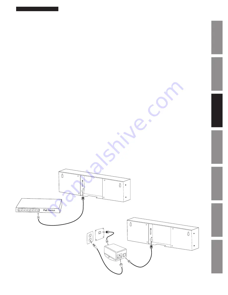
1. Apply power to the clock by connecting a CAT 5 (A) or higher Ethernet patch cable from a PoE switch (Fig. 1) or single
injector (Fig. 2) to the rear panel of the PoE clock. The time should display in less than one minute.
• PoE Switch: Check with the Network Administrator for infrastructure needs. This part is not supplied by American Time.
• PoE Injector (TMA200): This is an optional power source that may be purchased from American Time
Note:
When a DHCP network is not present at initial start-up, the PoE clock will default to a random Static IP in the range of
169.254.1.0 to 169.254.254.255.
If DHCP is enabled and the clock does not receive a DHCP IP or loses the IP, the following symptoms will occur:
–For 6 digit clocks, the seconds digits on the far right hand side of the clock will flash.
–For 4 digit clocks, the AM/PM indicators on the left side of the clock will flash
2. Upon startup the clock Firmware version and IP address will scroll across the display.
3. To adjust the Time Zone, push the Set button (B). Each button push will adjust the time by -1 hour.
Example:
If set to
Central Standard Time, push the button once for Mountain Standard Time.
4. Place the clock on the wall using the keyhole hanger (C) on the back of the clock. A mounting template is included with the
Quick Start Installation Guide.
Default Settings can be restored to the clock by:
1. Remove power to the clock for at least 2 seconds (disconnect the patch cable (A) from the back of the clock).
2. Hold down the Set button (B) on the back of the clock.
3. Apply power back to the clock (connect the powered patch cable to the clock) while continuing to hold down
the Set button.
4. 888 should scroll across the clock display.
5. Release the Set button.
Note:
The IP address set to the clock can be checked by quickly pressing the Set button (B) twice. The Set button is located on
the back of the clock next to the patch cable (A) plug-in. Once pressed the clock IP address will scroll quickly across the display.
A=PoE connection
(CAT 5 or higher Ethernet patch cable-supplied)
B=Set Button C=Keyhole hanger D=Relay
A
B
C
C
Fig. 1
D
Fig. 2
C
C
B
A
To local
power
(110vac)
TMA200
D


