background image


Chapter 2 AMIBIOS Setup     

63


Section 6


Peripheral Setup


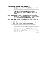
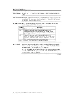
Choose Peripheral Setup from the AMIBIOS Setup main menu. All Peripheral 
Setup options are described below. 

Onboard FDC  

Set this option to 

Enabled

 to enable the floppy drive controller (FDC) on the 

motherboard. The settings are 

Auto (AMIBIOS automatically determines if the 

floppy controller should be enabled), Enabled,

 or 

Disabled.

 The Optimal and 

Fail-Safe default settings are 

Auto

.


Onboard Serial PortA 

This option specifies the base I/O port address of serial port 1. The 

settings are 

Auto (AMIBIOS automatically determines the correct base I/O port 

address), Disabled, 3F8h/COM1, 2F8h/COM2, 3E8h/COM3,

 or 

2E8h/COM4.


The Optimal and Fail-Safe default settings are 

Auto. 


Onboard Serial PortB 

This option specifies the base I/O port address of serial port 2. The 

settings are 

Auto (AMIBIOS automatically determines the correct base I/O port 

address), Disabled, 3F8h/COM1, 2F8h/COM2, 3E8h/COM3,

 or 

2E8h/COM4.


The Optimal and Fail-Safe default settings are 

Auto. 


Serial PortB Mode

 This option specifies the operating mode for serial port 2.This option appears 

only if the 

Onboard Serial PortB

 option is not set to 

Auto 

or

 Disabled.

 The 

settings are 

IrDA, ASK IR,

 or 

Normal.

 The Optimal and Fail-Safe default 

settings are 

Normal


IR Duplex Mode

 This option specifies the infrared transmission method. This option appears 

only if the 

Onboard Serial PortB

 option is not set to 

Auto 

or

 Disabled.

 The 

settings are 

Full 

or 

Half

. There are no default settings. 


Cont’d 

Summary of Contents for Olympus Pentium II

Page 1: ...Olympus Pentium II Pentium III PCI ISA Motherboard Guide MAN 781 6 24 99...

Page 2: ...held liable for any loss expenses or damages of any kind whatsoever whether direct indirect incidental or consequential arising from the design or use of this product or the support materials provide...

Page 3: ...figure 37 2 AMIBIOS Setup 39 AMIBIOS Setup Menu 40 Section 1 Standard Setup 41 Section 2 Advanced Setup 46 Section 3 Advanced Chipset Setup 51 Section 4 Power Management Setup 55 Section 5 PCI PnP Set...

Page 4: ...erboard and how to use the AMIBIOS that is specifically designed for this motherboard This manual is not meant to be read by the computer owner who purchases a computer with this motherboard It is ass...

Page 5: ...s part of a system manufactured by a company other than AMI or you purchased an AMI product from an unauthorized reseller Call the technical support department of the computer manufacturer or the unau...

Page 6: ...ill damage the motherboard Static Electricity The Olympus motherboard can easily be damaged by static electricity Make sure you take appropriate precautions against static electric discharge wear a pr...

Page 7: ...nology This motherboard supports Intel Pentium II Pentium III CPUs that include MMX support MMX technology allows you to experience richer video audio digital imaging and communications when running t...

Page 8: ...I Advanced Configuration and Power Interface support Expansion Slots The motherboard includes two 16 bit ISA expansion slots and five 32 bit PCI expansion slots The PCI local bus throughput can be up...

Page 9: ...mplemented remote ring on Your computer can be turned on from a remote location via a modem signal when the computer is in Sleep Mode This feature is useful if you are expecting a late night fax The o...

Page 10: ...CPU temperature returns to normal This feature can only be implemented if a power supply with a soft off power controller is installed in the computer High Voltage Protection The Olympus motherboard...

Page 11: ...nitoring and DMI features that permit continuous monitoring of key system performance parameters such as ambient temperature and cooling fan status AMIBIOS Features This motherboard has an AMIBIOS sys...

Page 12: ...2 devices Fast ATA The motherboard supports the Fast ATA specification using PIO mode 4 and multiword DMA mode 2 Ultra DMA 33 This motherboard includes an integrated enhanced IDE PCI bus master IDE c...

Page 13: ...SB peripherals are automatically detected and configured The AMIBIOS on this motherboard provides complete USB system BIOS support Power Connectors The Olympus motherboard has standard ATX power suppl...

Page 14: ...y configured by the AMIBIOS The PCI slots operate synchronously with the CPU clock as follows CPU External Clock Frequency PCI Expansion Slot Frequency 66 MHz 33 MHz 100 MHz 33 MHz Onboard I O The Oly...

Page 15: ...egatrends AMI_ClientCare utility is also shipped with this motherboard AMI_ClientCare allows you to display system information run diagnostic tests and display system environmental parameters such as...

Page 16: ...ntium III ISA Motherboard User s Guide 10 Olympus Dimensions Motherboard Height Restrictions The Altantis II motherboard measures 7 1 8 inches by 12 inches The areas on the motherboard with the height...

Page 17: ...tach cables to connectors Page 24 Connect the power supply Page 25 Attach the keyboard and mouse cables Page 25 Attach cables Page 26 8 Connect onboard I O Page 29 Connect the serial ports Page 29 Con...

Page 18: ...Olympus PCI Pentium II Pentium III ISA Motherboard User s Guide 12 Olympus Motherboard Layout...

Page 19: ...of the anti static mat Similarly a strip of conductive aluminum foil wrapped around the wrist and grounded through a 1 megohm resistor serves the same purpose as the wristband 3 Inside the carton the...

Page 20: ...rg 2 pin Berg In this manual jumpers are shown in two dimensions as if viewed from directly above as shown below 1 3 5 2 4 6 The placement of shunts is indicated by a solid line between pins as shown...

Page 21: ...rt Pins 2 3 Short Pins 2 3 AMD AM29F002T Short Pins 2 3 Short Pins 2 3 Avoid Static Electricity Static electricity can damage the motherboard and other computer components Keep the motherboard in the...

Page 22: ...CPU Switches 1 4 on SW1 are used to configure the internal frequency of the CPU Internal Frequency of CPU if Bus Frequency is 100 MHz Internal Frequency of CPU if Bus Frequency is 66 MHz SW1 Setting...

Page 23: ...nstall CPU Retention Mechanism Kit You must mount the Intel Retention Mechanism Kit before installing all Pentium II Pentium III CPU modules This kit includes the retention mechanism assembly attachme...

Page 24: ...Step 4 Install CPU Continued Install Retention Mechanism Place the retention mechanism on top of the CPU socket as shown below Install Attachment Mounts Place the two attachment mounts on the bottom o...

Page 25: ...inued Install the Heat Sink If the heat sink is not already installed on the CPU module slide the heat sink top support into the lowest gap on the CPU module as shown below Then slide the CPU module i...

Page 26: ...er s Guide 20 Step 4 Install CPU Continued Install the Heat Sink cont d Press the buttons on either side of the CPU module as shown below Hook the top support of the heat sink to the support base of t...

Page 27: ...MB 64 MB or 128 MB SDRAM PC100 DIMMs Supported System Memory Configurations DIMM1 DIMM2 DIMM3 DIMM43 Total System Memory 8 MB 8 MB 8 MB 8 MB 16 MB 8 MB 8 MB 8 MB 24 MB 16 MB 16 MB 16 MB 16 MB 32 MB 16...

Page 28: ...u firmly push the DIMM into the socket at an angle then push it up When properly inserted the DIMM clicks into place as the latching pins engage The DIMM installation process is shown below Memory Dis...

Page 29: ...cing you is where the motherboard is mounted The power supply is mounted at the far end of the chassis 3 Hold the motherboard component side up with the edge with the DIMM sockets toward you and the e...

Page 30: ...Keyboard Lock Page 29 Turbo LED lit when high speed is active Page 29 Suspend Mode Switch Page 29 Suspend LED lit when system in suspend mode Page 29 Serial Ports Page 29 Parallel Port Page 30 Floppy...

Page 31: ...power supply which should have built in filters to suppress radiated emissions Attach the power supply cables to the power connector on the motherboard ATX compatible power supplies have two 10 pin c...

Page 32: ...ed FAN1 attaches to the CPU fan The FAN1 connector is near the end of the CPU module socket Pin Description 1 Ground 2 12V 3 LM78 SENSE1 signal Chassis Fan A three pin berg labeled FAN2 attaches to th...

Page 33: ...e that supports the IrDA standards for infrared transmission The infrared connector pinout is Pin Description Pin Description 6 Ground 1 VCC 7 IRTX 2 VCC 8 IRTX 3 IRRX 9 VCC 4 FIRRX 10 VCC 5 Ground US...

Page 34: ...k connector is used to attach connectors to switches and LEDs on the front panel of the computer See page 12 for the location of the front panel connector Attach the cables from the IDE LED Power LED...

Page 35: ...IBIOS automatically checks the adapter cards installed in the expansion slots on the Olympus motherboard for a hard disk or floppy controller and serial or parallel ports Serial Ports COM1 and COM2 ar...

Page 36: ...The LPT pinout is shown below All parallel port settings can be configured through Peripheral Setup in AMIBIOS Setup Pin Signal Description Pin Signal Description 1 STROBE 2 PD0 3 PD1 4 PD2 5 PD3 6 PD...

Page 37: ...is installed Choose Standard Setup and Peripheral Setup to configure the floppy controller The motherboard supports up to two 720 KB 1 44 MB or 2 88 MB 3 drives and 360 KB and 1 2 MB 5 drives The conn...

Page 38: ...GND 6 DRATE0 7 GND 8 INDEX 9 GND 10 MOTOR0 11 GND 12 FDSEL1 13 GND 14 FDSEL0 15 GND 16 MOTOR1 17 GND 18 DIR 19 GND 20 21 GND 22 WDATA 23 GND 24 WGATE 25 GND 26 TRK0 27 GND 28 WRPROT 29 GND 30 RDATA 31...

Page 39: ...hapter 1 Hardware Installation 33 Step 10 Attach IDE Drive IDE Drives Attach the IDE drives in the following manner Choose Peripheral Setup in AMIBIOS Setup to enable the onboard IDE controller Cont d...

Page 40: ...IMARY as shown below PRIMARY is a 40 pin dual inline berg that connects an IDE drive to the primary onboard IDE connector This motherboard supports IDE Modes 0 1 2 3 and 4 IDE prefetch LBA Logical Blo...

Page 41: ...ATA0 18 DATA15 19 GND 20 KEY N C 21 N C 22 GND 23 IOW 24 GND 25 IOR 26 GND 27 IDERDY 28 ALE 29 N C 30 GND 31 INT14 32 IOCS16 33 HA1 34 N C 35 HA0 36 HA2 37 CS0 38 CS1 39 IDEACT 40 GND Secondary IDE Co...

Page 42: ...is Pin Use Pin Use 1 RESET 2 GND 3 DATA7 4 DATA8 5 DATA6 6 DATA9 7 DATA5 8 DATA10 9 DATA4 10 DATA11 11 DATA3 12 DATA12 13 DATA2 14 DATA13 15 DATA1 16 DATA14 17 DATA0 18 DATA15 19 GND 20 KEY N C 21 N...

Page 43: ...t if there are problems BIOS Errors If the system operates normally a display should appear on the monitor The BIOS Power On Self Test POST should execute If POST does not run successfully it will bee...

Page 44: ......

Page 45: ...provides power to CMOS RAM which retains the system parameters Every time the computer is powered on the computer is configured with the values stored in CMOS RAM by the system BIOS which gains contro...

Page 46: ...MOS SETUP ADVANCED CMOS SETUP ADVANCED CHIPSET SETUP POWER MANAGEMENT SETUP PCI PLUG AND PLAY SETUP PERIPHERAL SETUP AUTO DETECT HARD DISK CHANGE USER PASSWORD CHANGE SUPERVISOR PASSWORD CHANGE LANGUA...

Page 47: ...talled Sec Slave Not Installed Boot Sector Virus Protection Disabled Month Jan Dec ESC Exit Sel Day 01 31 PgUp PgDn Modify Year 1901 2099 F2 F3 Color Date Time Select Standard CMO Setup from the AMIBI...

Page 48: ...ed Choose Enabled to enable boot sector protection AMIBIOS displays a warning when any program or virus issues a Disk Format command or attempts to write to the boot sector of the hard disk drive If e...

Page 49: ...BIOS displays the drive parameters You can also change these parameters if you do not think AMIBIOS detected the drive parameters correctly or if you want to enable an enhanced IDE feature You can mod...

Page 50: ...mber on the disk surface where write precompensation begins Landing Zone This number is the cylinder location where the heads normally park when the system is shut down Sectors The number of sectors p...

Page 51: ...7 43 MB 22 733 5 300 733 17 30 MB 23 306 4 0 336 17 10 MB 24 925 7 0 925 17 54 MB 25 925 9 65535 925 17 69 MB 26 754 7 754 754 17 44 MB 27 754 11 65535 754 17 69 MB 28 699 7 256 699 17 41 MB 29 823 10...

Page 52: ...fy the type of standard PC drive that an ARMD drive will use when attached as a master or slave to the specified IDE channel The settings are Auto AMIBIOS automatically determines the correct type of...

Page 53: ...CDROM Try Other Boot Devices Set this option to Yes to instruct AMIBIOS to attempt to boot from any other drive in the system if it cannot find a boot drive among the drives specified in the 1st Boot...

Page 54: ...ard Disk Access Control This option specifies the read write access that is set when booting from a hard disk drive The settings are Read Write or Read Only The Optimal and Fail Safe default settings...

Page 55: ...s are Setup Boot To OS 2 Set this option to Yes if running OS 2 operating system and using more than 64 MB of system memory on the motherboard The settings are Yes or No The Optimal and Fail Safe defa...

Page 56: ...ntents of the video ROM cannot be read from or written to cache memory The Optimal and Fail Safe default settings are Cached C800 16K Shadow CC00 16K Shadow D000 16K Shadow D400 16K Shadow D800 16K Sh...

Page 57: ...t settings are Keyboard Port 64 60 Emulation The settings are Enabled or Disabled The Optimal and Fail Safe default settings are Disabled SERR Set this option to Enabled to enable the SERR signal on t...

Page 58: ...s are corrected by the chipset Corrected bits of data from memory are not written back to DRAM system memory If Level I is selected the J25 External SMI software jumper on the Series 745 board is disa...

Page 59: ...MB 128 MB or 256 MB The Optimal and Fail Safe default settings are 64 MB AGP Mlti Trans Timer AGP Clocks This option sets the AGP multi trans timer The settings are in units of AGP Clocks The settings...

Page 60: ...peF DMA BufferControl1 TypeF DMA Buffer Control2 These options specify the DMA channel where TypeF buffer control is implemented The settings are Disabled Channel 0 Channel 1 Channel 2 Channel 3 Chann...

Page 61: ...bled or Disabled The Optimal and Fail Safe default settings are Disabled Power Button Function This option specifies how the power button mounted externally on the computer chassis is used The setting...

Page 62: ...spend The Optimal default setting is Suspend The Fail Safe default setting is Disabled Hard Disk Time Out Minute This option specifies the length of a period of hard disk drive inactivity When this le...

Page 63: ...mal and Fail Safe default settings are Disabled Slow Clock Ratio This option specifies the speed at which the system clock runs in the Standby Mode power saving state The settings are expressed as a p...

Page 64: ...ing on the specified hardware interrupt request line If set to Monitor and the computer is in a power saving state AMIBIOS watches for activity on the specified IRQ line The computer enters the Full O...

Page 65: ...from the CPU on each set of palette registers on every video device Bit 5 of the command register in the PCI device configuration space is the VGA Palette Snoop bit 0 is disabled For example if there...

Page 66: ...or Slot5 If Auto is selected AMIBIOS automatically determines the correct setting The Optimal and Fail Safe default settings are Auto This option forces IRQ 14 and 15 to a PCI slot on the PCI local bu...

Page 67: ...t3 IRQ Priority PCI Slot4 IRQ Priority PCI Slot5 IRQ Priority These options specify the IRQ priority for PCI devices installed in the four PCI expansion slots The settings are Auto 3 4 5 7 9 10 11 12...

Page 68: ...configured as PCI PnP IRQ14 and 15 will not be available if the onboard Triton 2 PCI IDE is enabled If all IRQs are set to ISA and IRQ14 and 15 are allocated to the onboard PCI IDE IRQ9 will still be...

Page 69: ...COM3 or 2E8h COM4 The Optimal and Fail Safe default settings are Auto Onboard Serial PortB This option specifies the base I O port address of serial port 2 The settings are Auto AMIBIOS automatically...

Page 70: ...el Port EPP specification EPP uses the existing parallel port signals to provide asymmetric bidirectional data transfer driven by the host device ECP The parallel port can be used with devices that ad...

Page 71: ...Channel This option is available only if the setting for the Parallel Port Mode option is ECP This option sets the DMA channel used by the parallel port The settings are Auto DMA Channel 1 or 3 The O...

Page 72: ...h the Supervisor password or User password The Supervisor and User passwords activate two different levels of password security Set the Password Check option in Advanced Setup see the Advanced Setup s...

Page 73: ...assword prompt appears if the Password Check option is set to Always Change Supervisor Password Select Change Supervisor Password from the AMIBIOS Setup main menu Enter new supervisor password appears...

Page 74: ...guration with FailSafe Settings AMIBIOS will automatically set all AMIBIOS Setup options to a complete set of default settings when you choose this option The following appears Load Failsafe settings...

Page 75: ...eter To change a setting highlight the field to be changed Press or Ctrl to raise the value Press or Ctrl to lower a value Physical Parameter Low Alert High Alert Low Warning High Warning Current Valu...

Page 76: ...ble value for the associated parameter before an alert activity such as a series of beeps is taken by AMIBIOS High Alert This field contain the highest acceptable value for the associated parameter be...

Page 77: ...Flash EPROM based AMIBIOS The bootblock code immediately reads the A drive looking for the new BIOS information 4 When the flash ROM has successfully been programmed the computer will reboot Bootblock...

Page 78: ...attempts to read from floppy drive A 2 Look for S781P ROM on the floppy disk S781P ROM must be in the root directory of the floppy disk in drive A There is no beep if successful 3 Read the floppy dis...

Page 79: ...ep codes and when they can occur are Number of Beeps Description 1 Insert diskette in floppy drive A 2 The AMIBOOT ROM file was not found in the root directory of the diskette in floppy drive A 3 Base...

Page 80: ...the I O chipset if any E9h Program the CPU clock dependent chip set parameters EAh Enable the timer and the floppy diskette interrupt Enable the internal cache Copy the bootblock BIOS and pass control...

Page 81: ...ion 42 Boot To OS 2 49 Boot Up Num Lock 48 Bootblock BIOS Actions 71 Bootblock BIOS Code Sequence of Operation 72 Bootblock Code Checkpoint Codes 74 BX Master Latency Timer Clks 52 C Cables Connecting...

Page 82: ...rs 44 Hard Disk Drive Type D 43 Hard Disk Power Down Mode 56 Hard Disk Timeout Minute 56 Hardware Health Management Setup 69 Hardware Health Management Setup Fields 70 Hardware Reset Switch 29 Heat si...

Page 83: ...cation 8 PCI VGA Palette Snoop 59 PCI PnP Setup 59 PCI1 to PCI0 Access 52 Peripheral Setup 63 Onboard IDE 34 PERR 51 Physical Parameter 70 Pinout Parallel Port 31 Serial ports 30 PIO Mode 44 Plug and...

Page 84: ...48 System Management Interface 52 System Memory Configuring 22 T Tables Floppy pinout 33 Hard Disk Drive Types 45 I O conflicts 30 Steps for installing motherboard 24 Twist in floppy cable 33 Technic...

Page 85: ...Index 79...

Reviews: