background image


Chapter Three : AMIBIOS Setup 


85

Section 2


Advanced Setup, 

Continued


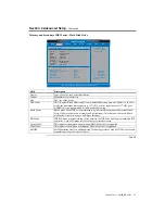
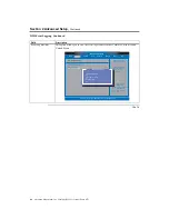
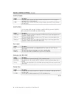
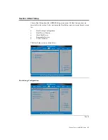
Hardware Health Configuration 


BIOS  SETUP UTILITY

v02.53  (C) Copyright  1985-2003, American Megatrends, Inc.

Main

Advanced

PCIPnP

Security

Exit

Power

Boot

Chipset

Select Screen
Select Item
Change Option
General Help
Save and Exit
Exit

+ -
F1
F10
ESC

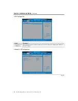
Hardware Health Configuratiion

Enables Hardware
Health Monitoring
Device.

H/W Health Function                                         [Disabled]

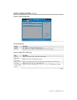
Hardware Health Event Monitoring


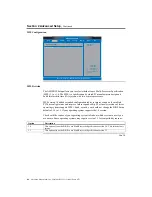
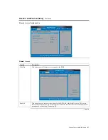
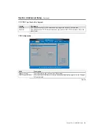
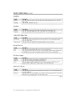
HW Health Function 


Option Description 

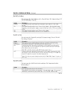
Disabled 

This option turns off hardware health monitoring 

Enabled 

This option turns on hardware health monitoring and is the default setting. 


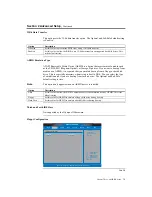
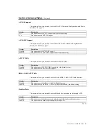
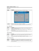
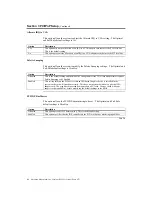
Hardware Health Event Monitoring 


Field Description 

System 
Temperature 

Displays the current internal system ambient temperature. 

CPU 
Temperature 

Displays the current CPU internal temperature. 
 

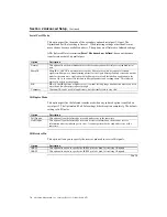
Fan1/2/3 Speed 

Displays the current speed of CPU cooling fan at JP2 and Auxiliary Fans at JP5 and JP6. 

CPU Core 

Displays the current CPU core actual voltage value. 

1.5V/3.3V/+12V
/+5.00V/5VSB/
Battery 

Displays the current voltage against the 1.5V/3.3V/+12V/+5V/5VSB/Battery power supply. 


Cont’d 

Summary of Contents for Olympus III

Page 1: ...Olympus III User s Guide MAN 875 02 02 04...

Page 2: ...Inc American Megatrends Inc acknowledges the following trademarks Intel is a registered trademark of the Intel Corporation MS DOS and Microsoft are registered trademarks of the Microsoft Corporation...

Page 3: ...ture CSA 9 Low Power Sleep Mode 9 Chapter 2 Hardware Installation 11 Overview 11 Motherboard Installation 11 Rear I O Ports 11 Motherboard Layout 12 Step 1 Unpack the Motherboard 13 Avoid Electro Stat...

Page 4: ...CI Slots 51 PCI IRQ Routing Table 51 Step 7 Connecting External Cables 53 LAN Connector 57 Serial Port Connector 58 VGA Connector 59 Line In Audio Jack 60 Speaker Out Audio Jack 61 Microphone Audio Ja...

Page 5: ...Advanced ACPI Configuration 80 ACPI 2 0 Support 81 ACPI APIC Support 81 APIC SCI IRQ 81 BIOS AML ACPI Table 81 Headless Mode 81 DMI Event Logging 82 Hardware Health Configuration 85 HW Health Functio...

Page 6: ...Boot Priority 100 CD DVD Drives Boot Priority 101 Section 5 Security Setup 102 Setting Up a Supervisor Password 102 Clearing the Password via BIOS 105 Clearing the CMOS via Hardware Jumper 108 Section...

Page 7: ...hanges 118 Discard Changes 119 Load Optimal Defaults 119 Load Failsafe Defaults 120 Chapter 4 Programming Flash ROM 121 A Programming the Flash EPROM Using Ctrl Home 121 Bootblock Actions 121 S875P RO...

Page 8: ...for AMI products purchased directly from AMI or from an AMI authorized reseller only If Then You purchased this product from AMI or from a certified AMI reseller Call AMI technical support at 770 246...

Page 9: ...he limitation or exclusion of liability for indirect special exemplary incidental or consequential damages in certain transactions therefore this statement may not apply to you Also you may have other...

Page 10: ...and found to comply with the limits for a Class A digital device pursuant to part 15 of the FCC Rules These limits are designed to provide reasonable protection against harmful interference when the...

Page 11: ...s 64 bits wide while the PCI bus is only 32 bits wide Theoretically the CSA bus has twice the bandwidth of a PCI bus This overcomes the bandwidth limitation found when running off of the PCI bus With...

Page 12: ...ware Monitor HECETE4 I2C Master Embedded in the Super I O SMBus Controller Embedded in the ICH5 System Monitors for the Following Devices One Chassis Fan Chassis Door Open Detection 1 CPU Fan One Ambi...

Page 13: ...9 J18 JP11 J17 SATA 1 SATA 0 USB 2 3 J20 JP6 JP8 JP1 JP2 JP5 JP7 8PIN POWER 24PIN POWER J2 DDR A DIMM 0 J3 DDR A DIMM 1 J4 DDR B DIMM 0 SOCKET 478 J5 DDR B DIMM 1 J6 SECONDARY IDE J5 PRIMARY IDE SERIA...

Page 14: ...American Megatrends Inc Olympus III User s Guide Series 875 4 Rear I O Ports...

Page 15: ...Kenai II CSA Giga Ethernet ATI VGA RAGE XL Audio Serial ATA 0 Serial ATA 1 USB 0 USB 1 USB 2 USB 3 Primary IDE Secondary IDE AMIBIOS 8 Super IO Keyboard COM 1 Mouse Floppy Parallel DDR400 CHA DIMM 0...

Page 16: ...ded or double sided DIMMs Double sided DIMMs with 16 chips are not supported A maximum of 4 GB of total system memory A minimum of 64 MB of total system memory ECC and non ECC DIMMs supported Serial P...

Page 17: ...M x 8 16 More Features Faster 128 bit dual channel DDR 400 memory support DDR 400 memory alone in single channel supports a maximum theoretical bandwidth of 3 2 GB s while a dual channel supports 6 4...

Page 18: ...is integrated support for a total of eight USB 2 0 ports ICH5 features two SATA channels supporting a maximum of two drives and two Parallel ATA channels supporting a maximum of four drives all of whi...

Page 19: ...PAT Increases memory and system level performance by optimizing internal data paths PAT speeds data flow between the processor and system memory to increase performance The 875P chipset also offers a...

Page 20: ...American Megatrends Inc Olympus III User s Guide Series 875 10...

Page 21: ...on Use the following steps to install the motherboard memory CPU and connectors Step Action 1 Unpack the Motherboard and check jumper settings 2 Install Memory 3 Install CPU and Connect CPU Heatsink a...

Page 22: ...1 J19 J18 JP11 J17 SATA 1 SATA 0 USB 2 3 J20 JP6 JP8 JP1 JP2 JP5 JP7 8PIN POWER 24PIN POWER J2 DDR A DIMM 0 J3 DDR A DIMM 1 J4 DDR B DIMM 0 SOCKET 478 J5 DDR B DIMM 1 J6 SECONDARY IDE J5 PRIMARY IDE S...

Page 23: ...acked in an anti static bag and sandwiched between sheets of packaging sponge Remove the sponge and the anti static bag Place the motherboard on a grounded anti static surface component side up Save t...

Page 24: ...ormal 1 2 3 Clear CMOS JP10 To drain CMOS RAM power perform the following steps Step Action 1 Turn off power to the computer 2 Remove the computer cover 3 Remove the jumper from pins 1 2 of JP10 4 Pla...

Page 25: ...DR333 SDRAM DIMMs Channel A CHA DIMM 0 Channel A CHA DIMM 1 Channel B CHB DIMM 0 Channel B CHB DIMM 1 The following table lists the supported FSB and memory speed combinations To use the FSB must be D...

Page 26: ...e Sided 256 Mbit 32 M x 8 32 M x 8 16 512 MB Single Sided 512 Mbit 64 M x 8 empty 8 1024 MB Double Sided 512 Mbit 64 M x 8 64 M x 8 16 Memory Configuration The Olympus III motherboard has the followin...

Page 27: ...Channel B CHB DIMM 0 Channel B CHB DIMM 1 Throughput Level Configuration Characteristics Highest Dual Channel with Dynamic Mode All DIMMs matched Second Highest Throughput Level Channel A CHA DIMM 0 C...

Page 28: ...DIMM 0 Channel B CHB DIMM 1 Throughput Level Configuration Characteristics Lower Single Channel with Dynamic Mode Single DIMM or DIMMs matched within a channel Lowest Throughput Level Channel A CHA DI...

Page 29: ...figuration section located on the previous pages Match the DIMM module and DIMM slot so that the notches align properly Insert the module by sliding it straight down into the slot Using your thumbs pr...

Page 30: ...st before the operating system boots The memory displayed by AMIBIOS on the System Configuration Screen is 384 KB less than the total memory installed Step 3 Install CPU and Connect Heatsink and Fan T...

Page 31: ...section is based on the common retail packaged Intel processor with heatsink fan combination For custom OEM configurations consult your CPU heatsink and cooling fan documentation Step Action 1 Lift th...

Page 32: ...s III User s Guide Series 875 22 Step 3 Install CPU and Connect Heatsink and Fan Continued Step Action 3 Once inserted depress the lever to secure the CPU to the ZIF socket 4 Apply silicon thermal gel...

Page 33: ...an Continued Step Action 5 To install the heatsink and cooling fan place the heat sink on top of the CPU and clip it to the ZIF socket Align the mounting bracket with the mounting clips of the heatsin...

Page 34: ...r s Guide Series 875 24 Step 3 Install CPU and Connect Heatsink and Fan Continued Step Action 7 Flip the two levers to secure the heatsink and cooling fan to the socket base 8 Connect the fan power ca...

Page 35: ...ere the motherboard is mounted The power supply is mounted at the far end of the chassis 3 Hold the motherboard with the component side facing up The printer serial VGA LAN and dual USB ports should b...

Page 36: ...les provided and tighten them If necessary shift the motherboard slightly to align the mounting holes on the motherboard with the holes on the chassis Warning If using metallic screws make sure you us...

Page 37: ...Power Connector 28 CN4 Serial ATA 0 Connector 42 CN5 Serial ATA 1 Connector 42 JP2 CPU Cooling Fan Connector 48 JP5 Auxiliary Cooling Fan Connector 49 JP6 Auxiliary Cooling Fan Connector 49 JP10 Clear...

Page 38: ...Olympus III motherboard ATX12V and EPS12V power supplies have an additional power lead that provides required supplemental power for the Intel Pentium 4 processor The Olympus III motherboard will not...

Page 39: ...ies often can run on a wide range of voltages and must be set usually via a switch to the proper range Use at least a 300 watt ATX power supply which should have built in filters to suppress radiated...

Page 40: ...Guide Series 875 30 Step 5 Attach Internal Cables Continued CN1 and CN2 ATX Power Supply Connectors Continued For 20 pin 4 pin ATX12V power supplies plug the connectors into pin one first as illustrat...

Page 41: ...tely wake a computer system A network adapter card that supports WOL has a very low power mode to monitor the network for a special data packet that can wake up the machine from standby mode commonly...

Page 42: ...connector is used strictly for debugging OEM custom configurations Contact your American Megatrends OEM sales representative for custom OEM design services Pin Signal Name Pin Signal Name 1 Ground 2...

Page 43: ...ted on your particular motherboard This connector is not described in this manual This connector is used strictly for OEM custom configurations Contact your American Megatrends OEM sales representativ...

Page 44: ...pansion card hard disk drive controller to use the same LED as the onboard IDE controller For proper operation this connector should be wired to the LED output of the expansion card hard disk drive co...

Page 45: ...be used to externally monitor FRUs Field Replaceable Units such as cooling fans power supplies and so on on the Olympus III motherboard through a management card such as the MegaRAC remote management...

Page 46: ...hip may or may not be mounted on your particular motherboard This connector and BMC chip is not described in this manual This connector is used strictly for debugging OEM custom configurations Contact...

Page 47: ...d J20 External Serial Port Connector J20 External Serial Port Connector Attach the external nine pin serial cable with a D type connector to jumper J20 Pin Signal Name Pin Signal Name 1 DSRB 2 DCDB 3...

Page 48: ...i BMC chip The physical connector and Hitachi BMC chip may or may not be mounted on your particular motherboard This connector and BMC chip is not described in this manual This connector is used stric...

Page 49: ...FDEDIN 7 Ground 8 FDINDX Index 9 Ground 10 FDM00 Motor Enabled A 11 Ground 12 No Connect 13 Ground 14 FDDS0 Drive Select A 15 Ground 16 No Connect 17 No Connect 18 FDDIR Stepper Motor Direction 19 Gro...

Page 50: ...5 Data 1 16 Data 14 17 Data 0 18 Data 15 19 Ground 20 Key 21 DDRQ0 22 Ground 23 I O Write 24 Ground 25 I O Read 26 Ground 27 IOCHRDY 28 P ALE Cable Select Pull up 29 DDACK0 30 Ground 31 IRQ 14 32 Rese...

Page 51: ...the AMIBIOS Setup utility from the IDE Configurations submenu in the Advanced section The IDE cable that is included with the Olympus III motherboard is a color coded 80 conductor 40 pin ATA 100 133...

Page 52: ...Serial ATA functionality is transparent to the operating system The Serial ATA controller can operate in both legacy and native Serial ATA modes In legacy mode standard resources are assigned such as...

Page 53: ...perate in parallel thus increasing the throughput Note The Olympus III motherboard provides support for RAID level 0 and RAID boot in Microsoft Windows XP only RAID Boot A RAID array can be created by...

Page 54: ...3 Reset Button 2 and 4 Parallel ATA Activity LED 5 and 7 Intrusion Sensor 8 and 10 Power LED 9 and 11 System Fault LED 13 and 15 Serial ATA Activity LED 16 and 18 The following is a diagram of the J1...

Page 55: ...GND NC SATA LED VCC 3V Power Button Attach your chassis power on off button switch to this section of the header Pin Signal Name 1 power 3 ground J19 Reset Button Connector 1 3 5 7 9 11 13 15 17 19 2...

Page 56: ...HDD Activity LED Attach your chassis HDD activity LED to this section of the header Check for the correct polarity Pin Signal Name 5 IDE LED 7 VCC 5 V J19 Intrusion Sensor Connector 1 3 5 7 9 11 13 1...

Page 57: ...sis power LED to this section of the header Check for the correct polarity Pin Signal Name 9 power LED 11 VCC 3 V J19 System Fault LED Connector 1 3 5 7 9 11 13 15 17 19 2 4 6 8 10 12 14 16 18 J19 PWR...

Page 58: ...R LED VCC 3V SF LED VCC 5V NC NC RST GND NC GND INT GND NC SATA LED VCC 3V Serial ATA Activity LED Attach your chassis Serial ATA HDD activity LED to this section of the header if applicable Check for...

Page 59: ...P5 and JP6 Auxiliary Cooling Fan Connector JP5 JP6 Auxiliary Cooling Fan Connector Auxiliary Cooling Fan Connector If your chassis has an internal chassis cooling fan you can attach the chassis coolin...

Page 60: ...Note AGP 2x expansion boards are NOT supported Read the documentation for the expansion board before installing it into the system For easier installation of your system memory install your system mem...

Page 61: ...uld not share an interrupt with other PCI devices Use the following information to avoid sharing an interrupt with a PCI add in card PCI devices are categorized as follows to specify their interrupt g...

Page 62: ...PIRQB PIRQC PIRQD PIRQE PIRQF PIRQG PIRQH AGP Connector INTA INTB USB Controller 1 INTA SMBus Controller INTB AC 97 ICH Audio Controller INTB USB Controller 2 INTB USB 2 0 Controller INTD PCI 0 INTD I...

Page 63: ...e system chassis such as fans and internal peripherals Do not use these connectors for powering devices external to the system chassis A fault in the load presented by the external devices could cause...

Page 64: ...875 54 Step 7 Connecting External Cables Continued PS 2 Keyboard Connector PS 2 Keyboard Connect your PS 2 keyboard into this port if applicable Pin Signal Name 1 Keyboard Data 2 Not Connected 3 Grou...

Page 65: ...Installation 55 Step 7 Connecting External Cables Continued Dual USB Connectors Dual USB 2 0 Connect your USB devices into this port if applicable Pin Signal Name 1 Fused 5 V 2 USBP0 USBP1 3 USBP0 US...

Page 66: ...PD2 5 PD3 PD3 PD3 6 PD4 PD4 PD4 7 PD5 PD5 8 PD6 PD6 PD6 9 PD7 PD7 PD7 10 ACK ACK INTR 11 BUSY BUSY PERIPHACK WAIT 12 PERROR PE ACKREVERSE PE 13 Select Select Select 14 AUDOFD AUDOFD HOSTACK DATASTB 1...

Page 67: ...stallation 57 Step 7 Connecting External Cables Continued LAN Connector 10 100 1000 NIC Connect your network cable into this jack if applicable Pin Signal Name 1 TX 2 TX 3 RX 4 Ground 5 Ground 6 RX 7...

Page 68: ...Serial Port Connector Serial Port Connect your serial device into this port if applicable Pin Signal Name 1 DCD Data Carrier Detect 2 DSR Data Set Ready 3 SIN Serial Data In 4 RTS Request to Send 5 SO...

Page 69: ...ternal Cables Continued VGA Connector VGA Connector Connect your monitor into this connector if applicable Pin Signal Name 1 Red 2 Green 3 Blue 4 5V 5 Ground 6 Ground 7 Ground 8 Ground 9 5V 10 Ground...

Page 70: ...III User s Guide Series 875 60 Step 7 Connecting External Cables Continued Line In Audio Jack Line In Connect your audio device into this jack if applicable Pin Signal Name 1 Line Right 2 Ground 3 Gro...

Page 71: ...Installation 61 Step 7 Connecting External Cables Continued Speaker Out Audio Jack Speaker Out Connect your speaker into this jack if applicable Pin Signal Name 1 Audio Right 2 Ground 3 Ground 4 Audio...

Page 72: ...bles Continued Microphone Audio Jack Microphone Connect your microphone into this jack if applicable Pin Signal Name 1 5V 2 Ground 3 Ground 4 Mic 5 Ground Step 8 Install Drivers Install the software d...

Page 73: ...st of the server board s components This chapter describes the parameters in the AMIBIOS Setup Utility and explains how to modify the settings for the configuration of your Olympus III motherboard Cau...

Page 74: ...02 53 C Copyright 1985 2003 American Megatrends Inc Power Boot Chipset Select Screen Select Item Change Field Select Field General Help Save and Exit Exit Tab F1 F10 ESC Use ENTER TAB or SHIFT TAB to...

Page 75: ...anufacturer information This field cannot be modified and is grayed out Processor Speed This field displays the speed of the processor This field cannot be modified and is grayed out Processor Count T...

Page 76: ...Exit Exit Enter Update F1 F10 ESC Ratio CMOS Settings 8 VID CMOS Settings 62 Configure Advanced CPU Settings Manufacturer Intel Brand String Intel R Pentium R 4 CPU 3 06GHz Frequency 3 06HHz FSB Speed...

Page 77: ...level three cache This is the default setting Hyper Threading Technology Hyper Threading Technology is the technology being built into many of Intel Pentium 4 processors It allows a single processor...

Page 78: ...Disk Write Protect Disabled IDE Detect Time Out Sec 35 ATA PI 80Pin Cable Detection Host Device P ATA S ATA This option turns on both parallel and serial ATA support in the BIOS BIOS SETUP UTILITY v0...

Page 79: ...hard disk location and CN5 SATA 1 as the forth hard disk location For the location of these two connectors see the Board Layout diagram in Chapter One Hardware Specifications and Supported Features T...

Page 80: ...wait twenty seconds when trying to detect the hard disk drives 25 This value allows the system to wait twenty five seconds when trying to detect the hard disk drives 30 This value allows the system to...

Page 81: ...ndor Manufacturer of the device Size The size of the device LBA Mode LBA Logical Block Addressing is a method of addressing data on a disk drive In LBA mode the maximum drive capacity is 137 GB For dr...

Page 82: ...oller As the PIO mode increases the cycle time decreases Async DMA This indicates the highest Asynchronous DMA Mode that is supported Ultra DMA This indicates the highest Synchronous DMA Mode that is...

Page 83: ...If supported set this value to allow the BIOS to auto detect the number of sectors per block for transfer from the hard disk drive to the memory The data transfer to and from the device will occur mu...

Page 84: ...DMA mode 0 It has a data transfer rate of 16 6 MBs It has the same transfer rate as PIO mode 4 and Multi Word DMA mode 2 UDMA1 Set this value to allow the BIOS to use Ultra DMA mode 1 It has a data tr...

Page 85: ...g to boot to DOS You can select the type of emulation used if you are booting from such a device The Optimal and Fail Safe default setting is Auto Note This option only appears when an ARMD device is...

Page 86: ...to allow the system to address the selected Floppy Drive location as a 1 44 MB 3 5 floppy drive 2 88 MB 3 5 Set this value to allow the system to address the selected Floppy Drive location as a 2 88 M...

Page 87: ...serial port to use 2E8 as its I O port address and IRQ 3 for the interrupt address If the system will not use a serial device it is best to set this port to Disabled Serial Port2 Address This option s...

Page 88: ...harp organizers and exchange data This Infrared protocol is widely used in Japan SIR SIR or Serial IR operates at higher rates It is meant for long range transmission where you need more than a few ch...

Page 89: ...ing Bi Directional This option allows data to be sent to and received from the parallel port EPP The parallel port can be used with devices that adhere to the Enhanced Parallel Port EPP specification...

Page 90: ...ptions Advanced ACPI Configuration Option Description Advanced ACPI Configuration This option allows you to enable or disable various ACPI Advanced Configuration and Power Interface support Advanced A...

Page 91: ...etting APIC SCI IRQ This option allows you to enable or disable APIC SCI IRQ Option Description Disabled This option turns off APIC SCI IRQ support and is the default setting Enabled This option turns...

Page 92: ...Clear Event Log Event Log Statistics Field Description View Event Logging This option allows you to read all comments stored in CMOS BIOS SETUP UTILITY v02 53 C Copyright 1985 2003 American Megatrend...

Page 93: ...ails Mark all unread events as read View Event Log Mark all events as read Clear Event Log Event Log Statistics Mark all events as read now Ok Cancel Clear Event Logs This option allows you to delete...

Page 94: ...C Copyright 1985 2003 American Megatrends Inc Main Advanced PCIPnP Security Exit Power Boot Chipset Select Screen Select Item Go to Sub Screen General Help Save and Exit Exit Enter F1 F10 ESC Event Lo...

Page 95: ...th Function Option Description Disabled This option turns off hardware health monitoring Enabled This option turns on hardware health monitoring and is the default setting Hardware Health Event Monito...

Page 96: ...ntel architecture IA systems with two or more processors MPS version 1 4 added extended configuration tables to improve support for multiple PCI bus configurations and improve future expandability Mos...

Page 97: ...t Enabled COM1 XXXXX X X X None Disabled ANSI Disabled Remote Access Option Description Disabled This option turns off remote access support in the BIOS BIOS SETUP UTILITY v02 53 C Copyright 1985 2003...

Page 98: ...00 8 n 1 This value allows the serial port to transfer data at 19200 bits per second using eight data bits no parity bit and one stop bit This is the default value Flow Control Option Description None...

Page 99: ...erican Megatrends Inc Main Advanced PCIPnP Security Exit Power Boot Chipset Select Screen Select Item Change Option General Help Save and Exit Exit F1 F10 ESC USB Configuration Enables USB host contro...

Page 100: ...This is the default value Legacy USB Support Option Description Enabled Set this value to allow the system to use legacy USB devices such as a USB keyboard and a USB mouse This is the default value Di...

Page 101: ...ause system to malfunction Plug and Play O S Option Description No This value allows the BIOS to configure the devices in the system This is the default value Yes This value allows the operating syste...

Page 102: ...Description Disabled This is the default setting and should not be changed unless the VGA card manufacturer requires Palette Snooping to be Enabled Enabled This setting informs the PCI devices that an...

Page 103: ...ot 3 Use this value if you have installed a PCI IDE expansion board in PCI slot labeled PCI2 on your motherboard PCI Slot 4 Use this value if you have installed a PCI IDE expansion board in PCI slot l...

Page 104: ...5 DMA Channel 0 DMA Channel 1 DMA Channel 3 DMA Channel 5 DMA Channel 6 DMA Channel 7 Reserved Memory Size Auto Available Available Available Available Available Available Available Available Availabl...

Page 105: ...t Exit Enter F1 F10 ESC Boot Settings Configuration Boot Device Priority Hard Disk Drives Removable Drives CD DVD Drives Configure Settings during System Boot Boot Settings Boot Settings Configuration...

Page 106: ...otup Num Lock Option Description On This value turns on the NUM LOCK at boot This is the default value Off This value turns off the NUM LOCK at boot The number lock can be instated at anytime after th...

Page 107: ...m checks for the device to boot from To access this screen select Boot Device Priority on the Boot Setup screen and press Enter The following screen displays BIOS SETUP UTILITY v02 53 C Copyright 1985...

Page 108: ...vice Network BIOS SETUP UTILITY v02 53 C Copyright 1985 2003 American Megatrends Inc Main Advanced PCIPnP Security Exit Power Boot Chipset Select Screen Select Item Change Option General Help Save and...

Page 109: ...ve 2nd Drive 3rd Drive 4th Drive Specifies the boot sequence from the available devices Hard Disk Drives HDD PM Maxtor 4G16 SCSI 01 39160 B 00 SCSI 01 39160 B 02 SCSI 01 39160 B 08 BIOS SETUP UTILITY...

Page 110: ...rends Inc Main Advanced PCIPnP Security Exit Power Boot Chipset Select Screen Select Item Change Option General Help Save and Exit Exit F1 F10 ESC 1st Drive Specifies the boot sequence from the availa...

Page 111: ...rends Inc Main Advanced PCIPnP Security Exit Power Boot Chipset Select Screen Select Item Change Option General Help Save and Exit Exit F1 F10 ESC 1st Drive Specifies the boot sequence from the availa...

Page 112: ...ssword Install or Change the password Security Settings Setting Up a Supervisor Password Follow the instructions below to setup a supervisor level password on your Olympus III motherboard Step Action...

Page 113: ...Password Not Installed User Password Not Installed Change Supervisor Password Change User Password Clear User Password Install or Change the password Security Settings Enter New Password 3 The Confirm...

Page 114: ...pervisor password is Installed BIOS SETUP UTILITY v02 53 C Copyright 1985 2003 American Megatrends Inc Main Advanced PCIPnP Security Exit Power Boot Chipset Select Screen Select Item Change General He...

Page 115: ...F1 F10 ESC Supervisor password Installed Setup Change Supervisor Password Password Check Install or Change the password The Change Supervisor Password option is highlighted in white Press the ENTER ke...

Page 116: ...ESC Supervisor password Installed Setup Change Supervisor Password Password Check Install or Change the password Enter New Password 4 The Password Uninstalled prompt appears Press the ENTER key to re...

Page 117: ...5 2003 American Megatrends Inc Main Advanced PCIPnP Security Exit Power Boot Chipset Select Screen Select Item Change General Help Save and Exit Exit Enter F1 F10 ESC Supervisor Password Not Installed...

Page 118: ...Chipset Setup Choose Chipset Setup from the AMIBIOS Setup Utility main menu The screen is shown below All Chipset Setup options are described following the screen This menu allows you to configure the...

Page 119: ...ts the performance parameters of the installed memory chips DRAM Do not change the value from the factory setting unless you install new memory that has a different performance rating Option Descripti...

Page 120: ...tor situations PCI This value allows the monitor connected to the PCI graphics card to be the first monitor to display in multiple monitor situations Graphics Aperture Size Memory mapped and graphics...

Page 121: ...used by the system All system resources are freed Enabled This value turns on the onboard VGA chip This is the default value South Bridge Chipset Configuration SouthBridge Chipset Configuration v02 53...

Page 122: ...y Time Out Suspend Time Out Throttle Slow Clock Ratio Keyboard PS 2 Mouse FDC LPT COM Ports Primary Master IDE Primary Slave IDE Secondary Master IDE Secondary Slave IDE System Thermal Power Button Mo...

Page 123: ...monitor but this setting uses less power than Standby mode This is the default setting Hard Disk Power Down Mode This option specifies the power conserving state that the hard disk drive enters after...

Page 124: ...fe default settings is 50 Option Description 87 5 This setting allows the BIOS to throttle back the CPU clock to operate 87 5 percent of the time 75 0 This setting allows the BIOS to throttle back the...

Page 125: ...Thermal Slow Clock Ratio field 55C 131F A temperature reading higher that 55 degrees C and 131 degrees F will generate a power management event The CPU clock will throttle back a certain percentage a...

Page 126: ...to throttle back the CPU clock to operate 25 percent of the time 12 5 This setting allows the BIOS to throttle back the CPU clock to operate 12 5 percent of the time Power Button Mode This option spec...

Page 127: ...of the AMIBIOS Setup Utility All Exiting options are described in this section The Exit screen is displayed below BIOS SETUP UTILITY v02 53 C Copyright 1985 2003 American Megatrends Inc Main Advanced...

Page 128: ...l Defaults Load Failsafe Defaults Exit system setup after saving the changes F10 Key can be used for this operation Exit Options Save configuration changes and exit setup Ok Cancel Exit Discarding Cha...

Page 129: ...lly sets all options to a complete set of default settings when you select this option The Optimal settings are designed for maximum system performance but may not work best for all applications In pa...

Page 130: ...ystem configuration problems Select Load Fail Safe Defaults from the Exit menu and press Enter Click on Ok to load Fail Safe defaults BIOS SETUP UTILITY v02 53 C Copyright 1985 2003 American Megatrend...

Page 131: ...hen the flash ROM has successfully been programmed the motherboard will reboot 6 When the motherboard reboots check the BIOS Release text at the bottom of the first boot screen to make sure that the c...

Page 132: ...of beeps during Flash ROM programming to signify completion of a step as shown on the previous page or to signal an error Error beeps are arranged in a coded sequence and have different meanings depe...

Page 133: ...ompted to save or delete the existing BIOS Enter Y if you want to save the existing BIOS ROM or N if you do not Help Error Message Press ESC to Exit AMIFLASH Version x xxx Flash Programming Utility Co...

Page 134: ...tel 4Mb Firmware Hub Flash ROM present Enter the Filename to which Existing BIOS will be saved The Format Drv Pathname Filename Ext The Filename must end with a ENTER Enter the BIOS filename from whic...

Page 135: ...lash 5 At the prompt Program Boot Block type Y and press Enter 6 After the boot block is programmed reboot the system 7 Turn the power off Enter Y if you want to program the boot block or N if you do...

Page 136: ...the I O chipset if any E9h Program the CPU clock dependent chip set parameters EAh Enable the timer and the floppy diskette interrupt Enable the internal cache Copy the boot block BIOS and pass contr...

Page 137: ...m the following steps to erase the old password Important Make sure you are properly grounded before performing the following procedure You must be certain that no electrostatic discharge ESD occurs E...

Page 138: ...American Megatrends Inc Olympus III User s Guide Series 875 128...

Page 139: ...ve 5 years depending on how you use the system This battery location is shown in the illustration below BT1 CR2032 3V Battery American Megatrends suggests that you replace this battery with a coin typ...

Page 140: ...American Megatrends Inc Olympus III User s Guide Series 875 130...

Page 141: ...r beep code 8 these codes are always fatal Troubleshooting AMIBIOS Beep Codes For 1 beep 2 beeps or 3 beeps try reseating the memory first If the error still occurs replace the memory with known good...

Page 142: ...missing CPU BIOS chip or Chipset chip will cause the motherboard not to function Next eliminate the possibility of interference by bad or improperly setup I O cables by removing all cards and cables e...

Page 143: ...oid Electro Static Discharge ESD 13 B Battery 85 129 Battery Replacement 129 Beep Codes 122 BIOS AML ACPI Table 81 Block Multi Sector Transfer 73 Block Diagram 5 Board Layout 3 69 Boot Device Priority...

Page 144: ...ATX Power Supply Soft ON OFF Connector 45 J19 Front Panel Connector 44 J19 Intrusion Sensor Connector 46 J19 Parallel ATA Activity LED Connector 46 J19 Power LED Connector 47 J19 Reset Button Connect...

Page 145: ...105 106 107 108 Serial ATA SATA support 8 Serial ATA RAID 43 52 Serial Port Connector 27 58 Serial Port Mode 88 Serial Port Number 88 Serial Port1 Address 77 Serial Port2 Address 77 Serial Port2 Mode...

Page 146: ...American Megatrends Inc Olympus III User s Guide Series 875 136...

Reviews: