


R
EV
9
37
A
MERICAN
M
AGNETICS
, I
NC
.
I
NSTALLATION
: S
YSTEM
I
NTERCONNECTS
(M
ULTI
-A
XIS
S
YSTEMS
)
S
YSTEM
I
NTERCONNECTS
(M
ULTI
-A
XIS
S
YSTEMS
)
G
ENERAL
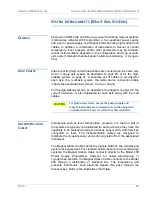
Each axis of AMI’s two and three axis superconducting magnet systems
incorporates a Model 430 Programmer, a four-quadrant power supply,
and a set of power-supply and magnet interconnecting high-current load
cables. In addition, a combination of instruments to monitor or control
temperature, level, pressure and/or other parameters may be included.
Actual instrumentation depends on the configuration and type of multi-
axis system (standard helium-based, helium-recondensing, or cryogen-
free).
L
OAD
C
ABLES
Interconnecting high-current load cables are connected in the same way
as for a single axis system as described on page 28, or for the high-
stability system on page 31. A separate set of cables is provided for
each axis of a multi-axis system; the cable device connection labels
include the associated axis (Z-axis, Y-axis, or X-axis).
For the high-stability system, as depicted in the diagram on page 32, the
current transducer
is also duplicated for each axis along with the load
cables.
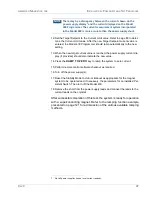
CAUTION
For multi-axis systems, ensure the power supply and
magnet load cables are connected only to the equipment
associated with the axis for which the cable is labeled.
I
NSTRUMENTATION
C
ABLES
Instruments such as level, temperature, pressure, etc. that are part of
the system are typically not duplicated for each axis since they have the
capability to be switched among the various sensor and control devices
connected to them. The instrumentation cables are designed to
distribute the cryostat sensor and control signals to/from the associated
instrument.
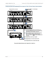
The Magnet Station Cable carries the signals between the cryostat and
system rack equipment. For standard helium-based (non-recondensing)
systems, the Magnet Station Cable connects directly to the Model 430
Power Supply Programmer. However, for helium-recondensing or
cryogen-free systems, the Magnet Station Cable connects to the Model
430 through a distribution or breakout box. The temperature and
pressure instruments have electrical signals that pass through the
breakout box. Refer to the illustrations that follow.
Summary of Contents for 430
Page 2: ......
Page 16: ...XVI REV 9 AMERICAN MAGNETICS INC FOREWORD SAFETY SUMMARY ...
Page 28: ...12 REV 9 AMERICAN MAGNETICS INC INTRODUCTION OPERATING CHARACTERISTICS ...
Page 64: ...48 REV 9 AMERICAN MAGNETICS INC INSTALLATION POWER UP AND TEST PROCEDURE ...
Page 208: ...192 REV 9 AMERICAN MAGNETICS INC SERVICE RETURN AUTHORIZATION ...
Page 248: ...232 REV 9 AMERICAN MAGNETICS INC APPENDIX SHORT SAMPLE MODE ...


