background image

RM4200 Series User Guide

RM4210 & RM4211 Installation

12

Installation Requirements

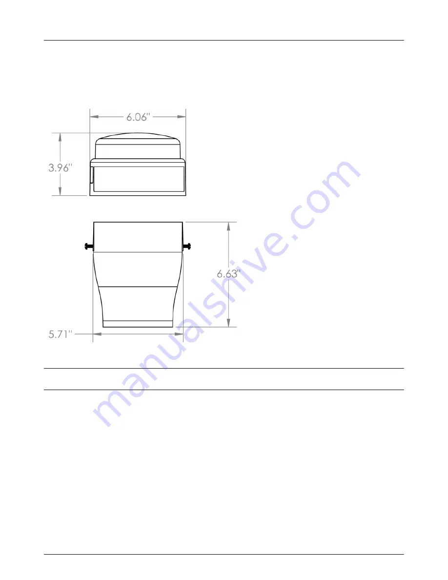
The RM4210 and RM4211 remote monitoring units (RMUs) are designed to be installed on top of a test station 
using an adapter. The dimensions of the unit and test station adapter are shown below.

Figure 2-4.   RMU Enclosure and Adapter Dimensions

N

OTE

:

The test station adapter is designed to fit on test stations with a 3” diameter.

The list below identifies conditions to consider before installing the unit. 

The area around the installation site should provide enough working space to easily access the unit to 
wire inputs, configure the unit for service and take measurements, or perform routine maintenance.

The RMU should be placed in an area that is clear of obstructions that may interfere with satellite 
reception. The RMU connects to the satellite that is directly south of North America


(the satellite’s 

coverage is shown in light blue on the map). Satellite signal strength can be verified before completing 
installation (refer to 

Installing the RM4211, 

page 18).

Summary of Contents for Bullhorn RM4200 Series

Page 1: ...Bullhorn RM4200 Series User Guide RM4200 Series User Guide Proven compliance solutions Proven compliance solutions Relentless service ...

Page 2: ... the written permission of American Innovations is strictly forbidden The American Innovations logo and icon including Bullhorn are marks of American Innovations Ltd Other trademarks and trade names may be used in this document to refer to either the entities claiming the marks and names or their products American Innovations Ltd disclaims any proprietary interest in trademarks and trade names oth...

Page 3: ...ine 7 Technical Services 7 CHAPTER 2 RM4210 RM4211 Installation 8 Overview 8 RM4210 Inputs 9 RM4211 Inputs 10 Preparing for Installation 10 Electrostatic Discharge 11 Installation Requirements 12 Installation Overview 13 Installing the RM4210 14 Installing the RM4211 18 Testing Satellite Reception 23 Maintenance 24 CHAPTER 3 Configuration 25 Configuration Overview 25 Disabling Synchronization Soft...

Page 4: ...7 Renaming or Deleting Templates 47 Scaling 47 Setting Up Inputs and Alarms 47 Switching Over Current 49 Setting a Transmission and Measurement Schedule 49 Viewing Battery Information 50 Updating Firmware 50 Viewing Unit Information or Emailing Support 50 Exit Bullhorn Tools 51 Appendix A Technical Specifications 52 Appendix B Optional Installations 54 Precautions for Connecting Optional Component...

Page 5: ...ange Notes The following list identifies new or updated information included in the current release of this manual Chapter 2 RM4210 RM4211 Installation on page 8 New installation instructions for the RM4211 ...

Page 6: ...nsys com This guide provides the following information Chapter 1 Getting Started Chapter 2 RM4210 RM4211 Installation Chapter 3 Configuration NOTE The Bullhorn RM4200 Series User Guide and other related documentation can be downloaded in Adobe PDF format from Bullhorn Web under the Help menu Use Adobe Reader version 5 or higher to view the PDF If needed visit the Adobe website at http www adobe co...

Page 7: ...observe this warning may result in personal injury death or equipment damage A potential risk exists if the installation instructions are not followed Warning Risk of electrical shock Failure to observe this warning may result in personal injury death or equipment damage A potential risk exists if the installation instructions are not followed Earth ground terminal Indicates a protective earth gro...

Page 8: ... Reports and extracts are also available through the Bullhorn Web account to view the data from your units The RM4210 inputs can be measured and configured locally using either the Bullhorn Tools software on a laptop or with the mobile application on a smartphone or tablet running either iOS or Android The RM4211 can be configured only with the mobile app The Bullhorn Tools software is available f...

Page 9: ...umber 211061 000 Belden 5308UE or its equivalent All cables must have intact outer jackets except for end cuts Do not remove cable jackets as they protect the unit input cable from transient voltages Cable insulation should be suited for voltage range of inputs Cables should be rated at a minimum of 600 V and 105 C Input Channel Voltage Levels All input channels are marked with acceptable input vo...

Page 10: ...rsion 8 0 or higher Adobe Reader version 6 0 or higher A smartphone or tablet with the following iOS 8 1 or later verify version through Settings General About Bluetooth Bullhorn Tools Mobile application available through the Apple App Store or Google Play Store NOTE While the RM4210 can be configured with either the software version or mobile app the RM4211 can only be configured with the mobile ...

Page 11: ...osoft NET Framework visit the Microsoft website at the following web address http www microsoft com Installing Bullhorn Tools Bullhorn Tools is available in software form installed on a computer and as a mobile app installed on a mobile device and is used to configure Bullhorn RMUs for service Bullhorn Tools can also be used to view unit information and to create settings templates which can be us...

Page 12: ...ess 1 to access the packet log when prompted 3 Use your telephone keypad to enter the unit serial number when prompted The unit serial number is included on the bar code label on the unit It is also included on the label of the shipping carton If required repeat this step to check another unit Technical Services If you need assistance with the installation or configuration contact American Innovat...

Page 13: ...t sales aiworldwide com Refer to Appendix A Technical Specifications on page 52 for details on the input ratings accessories and part numbers WARNING If the RM4210 or RM4211 are used in a manner not specified by American Innovations the protection provided by the equipment may be impaired Overview RM4210 and RM4211 units are housed in a weatherproof enclosure The unit and test station adapter are ...

Page 14: ... max Test Coupon 2 100 V max Test Coupon 1 0 2 A max AC Coupon 0 2 A max Structure 0 2 A max NOTE The battery is the only field serviceable item in the RM4210 After the unit is connected to the test station head the RM4210 can be configured with Bullhorn Tools configuration software or with the Bullhorn Tools mobile application Bullhorn Tools can display measurements set alarms or send a test mess...

Page 15: ...wing image shows the input connections and battery placement for the RM4211 Figure 2 3 RM4211 Inputs and Batteries The RM4211 includes the following inputs CH1 100 V max CH2 100 V max CH3 100 V max Switch 0 2 A max Preparing for Installation WARNING Only accessories that meet American Innovations specifications may be used with the RM4211 Refer to Appendix A Technical Specifications on page 52 for...

Page 16: ...allation The mobile application can be downloaded from the Apple App Store or Google PlayTM Electrostatic Discharge Electrostatic Discharge ESD can damage electronic components Provide ESD protection by wearing an anti static wrist strap attached to any unpainted metal surface before making contact with any internal components If an anti static wrist strap is unavailable discharge static electrici...

Page 17: ...ow identifies conditions to consider before installing the unit The area around the installation site should provide enough working space to easily access the unit to wire inputs configure the unit for service and take measurements or perform routine maintenance The RMU should be placed in an area that is clear of obstructions that may interfere with satellite reception The RMU connects to the sat...

Page 18: ...allation section for instructions Installing the RM4210 Installing the RM4211 The following steps provide an overview of a typical installation as well as the recommended installation sequence 1 Determine where to place or mount the RMU 2 Make connections to the test station 3 Install test station adapter 4 Make connections to the RMU 5 Test satellite communications 6 Secure the RMU 7 Configure th...

Page 19: ...valent for wiring inputs To ensure a clean stable reading keep field wiring as short as possible and use shielded twisted pair wire such as Alpha 2463C Complete the following steps to install the RM4210 on a coupon test station NOTE For the RM4210 you can attach either a PCR or a selectable current transducer attached to a PCR Refer to Installing the Selectable Current Transducer section in Append...

Page 20: ...lockwise to secure the adapter onto the test station 5 Drop the tether cord attached to the RM4210 down into the test station Ensure the tether end catches across the diameter of the test station The tether will be used to support the unit if the test head needs to be accessed at a later time Figure 2 7 Test Station Adapter 6 Install the batteries into the bracket inside the RM4210 Secure with str...

Page 21: ...l to the corresponding connection on the RM4210 board Figure 2 9 RM4210 8 pin Connector 8 OPTIONAL connect a solar panel or DC input to the DC Solar connector on the RM4210 board Refer to Appendix B Optional Installations on page 54 for instructions 9 Connect the two battery connectors to the battery connections on the RM4210 board ...

Page 22: ...indicates the unit is powered on NOTE If you are unsure of satellite coverage or if the unit is placed in an area that is heavily covered by foliage first check satellite reception by completing the steps in the Installing the RM4211 section When finished complete the installation procedures 10 Place the RM4210 onto the test station adapter carefully wrapping the wiring harness inside the dome Ali...

Page 23: ...for service Installing the RM4211 IMPORTANT Electrostatic Discharge ESD can damage electronic components Provide ESD protection by wearing an anti static wrist strap attached to any unpainted metal surface before accessing the unit or handling electronic parts If an anti static wrist strap is unavailable discharge static electricity from yourself and your clothing by touching a nearby metal surfac...

Page 24: ...e the protective cover over the test station head 2 Connect wiring harness individual wires to the respective test points on the test station Figure 2 12 Wiring Harness Leads The wires are color coded and labeled for use with a Triton coupon test station If connecting to another type of test station note the following The blue and red Test Cpn leads must be on the same connection 3 For Triton coup...

Page 25: ...13 Test Station Adapter NOTE The RM4211 can also be attached to the test station s riser post with a circular clamp and adjustable bracket 5 Install the batteries into the bracket inside the RM4211 Secure with strap Figure 2 14 Battery Bracket and Battery Placement ...

Page 26: ...4211 board Refer to Appendix B Optional Installations on page 54 for instructions 8 Connect the two battery connectors to the battery connections on the RM4211 board Figure 2 16 Battery Connections Connect the larger round battery to the P4 connection Connect the bundled pair of batteries to the P3 connection The RM4211 makes a clicking sound after connecting the batteries This is a normal functio...

Page 27: ... wrapping the wiring harness inside the dome Align the cut out below the Bullhorn label on the dome to the screw next to blue dot on the adapter Figure 2 17 Adapter with Blue Sticker for Alignment with Unit Dome 10 Secure the unit by tightening the screws IMPORTANT Do not twist the dome on the adapter if the cut outs do not line up with the screws Lift the dome off of the adapter and replace it in...

Page 28: ...g in Bullhorn Tools Mobile which will include unit information and a log file with your email 1 Activate the unit by swiping a magnet across the access point on the unit marked with an arrow on the enclosure A red light flashes to indicate that the unit is waiting to pair with your device Once the unit has paired with your device the light will stop flashing and remain on Figure 2 18 RMU Access Po...

Page 29: ...e or tap to see Radio SNR 6 Click or tap Send Test Message to update the Radio SNR reading To ensure proper communication with the satellite the Radio SNR reading should be at least 40 dB Also refer to Sending a Test Message page 29 Maintenance If performing maintenance on the RM4210 or RM4211 first disconnect the equipment from hazardous voltages before gaining access to the enclosure ...

Page 30: ...or later or Android 7 or later For complete instructions on using the Bullhorn Tools Mobile app to configure either RM4210 or RM4211 refer to the Bullhorn Tools Mobile User Guide which can be viewed or downloaded from the Bullhorn Web help page After configuring your unit unit information and settings can be accessed through your Bullhorn Web https www bullhornsys com account Configuration Overvie...

Page 31: ...hat the unit is waiting to pair with a Bluetooth enabled device Once the unit has paired with your device the light will stop flashing and remain on Figure 3 1 RMU Access Point Activated NOTE The unit will stop waiting to pair light flashing after 10 minutes It is not necessary to swipe the activation point again unless you wish to de activate the Bluetooth connection immediately Configure your un...

Page 32: ...t to Bullhorn Web and when measurements will be taken by the unit You can create and apply either one or two measurement schedules to a Reading Setting Battery Information Set an install date and battery type for the unit Editing Settings for Coupon Transducer and Instant Off Edit the settings for these inputs Selecting Reading Measurement Schedules Select one or two measurement schedules for desi...

Page 33: ...o update Readings Figure 3 3 RM4210 Unit Overview Window Viewing Unit Information Use the following steps to check unit and communications information 1 Click the name of the unit in the navigation pane to view Readings Test Message Status Power Relay States Unit Information Reporting Test Coupon and Triton Coupon panes ...

Page 34: ...surements with the coupon size applied Sending a Test Message Complete the following steps to send a test message to the Bullhorn Web account 1 Click Send Test Message or click Action Send Test Message 2 When an Info dialog box displays click OK Figure 3 5 Test Message Requested The Unit Overview Test Message Status pane updates the status of the test message ...

Page 35: ...ress When the test message has been successfully sent the status updates to Transmission Successful Figure 3 7 Test Message Status Transmission Successful A packet is sent to your Bullhorn Web account with current data point information View the packet labeled Test on the Unit Detail page under the Incoming Packets tab Figure 3 8 Unit Detail on Bullhorn Web ...

Page 36: ...s to create a new template 1 Click File Create Template 2 Enter a name for the new template in the Name field Figure 3 9 Create New Template Applying a Template If a template is available for the unit type you plan to configure you can apply the template to the current unit You can also import a saved template to Bullhorn Tools and then apply it to the current unit For information on how to export...

Page 37: ... Template Management to import export or delete saved templates For information on how to import a saved template refer to Complete the following steps to export or delete a template 1 Click File Template Management Figure 3 11 Template Management 2 To export a saved template to your computer as a Bullhorn Template bht file a Select the template from the Select template drop down list b Click Expo...

Page 38: ...RM4200 Series User Guide Configuration 33 Figure 3 12 Select Template The settings used with the template display Figure 3 13 Template Settings 5 Verify unit settings then click Apply ...

Page 39: ...coming Packets tab Figure 3 14 Incoming Packets Tab Also on the Reporting Power window you can set when and how often measurements are taken and stored in the data log The data log will be transmitted to your Bullhorn Web account during the scheduled transmission time You can create two different measurement schedules that can be applied individually or together for any Reading Occasionally the un...

Page 40: ...ing Power window Figure 3 15 Reporting Power Window 2 For the transmission settings select an interval from the Maximum Interval drop down list 3 For all interval options enter a time of day to send the transmission in the Start Time field The time defaults to AM To change to PM type PM next to the time 4 For Day of the Month interval select up to four days from the calendar shown ...

Page 41: ...ement Schedule 1 and or Measurement Schedule 2 for when measurements will be taken select an interval from the Interval drop down list 7 For all interval options enter a time of day to take the measurements in the Start Time field The time defaults to AM To change to PM type PM next to the time 8 For Day of the Month interval select up to four days from the calendar shown Figure 3 18 Day of Month ...

Page 42: ...t Schedules 10 Click Save to save settings or Cancel to clear all fields Setting Battery Information Battery information includes an installation date and battery type This information is set when the unit is manufactured at American Innovations Complete the following steps to edit battery information 1 Click Reporting Power The Reporting Power window displays ...

Page 43: ...igure 3 20 Reporting Power Window 2 Enter or select an installation date in the Battery Install Date field 3 Select a battery type from the Battery Type field The default is Lithium Ion 4 Click Save to save settings or Cancel to clear all fields ...

Page 44: ...utput Transducer corresponding transducer measurement value at maximum transducer voltage output Instant Off the wait time to take an instant off voltage measurement after cathodic protection has been interrupted through an internal relay Complete the following steps to set the settings for coupon transducer and instant off 1 Click Settings The Settings window displays Figure 3 21 Settings for Cou...

Page 45: ...suring current the Measurement Label for the AC Drain Current displayed value on Bullhorn Web can be changed to a different unit of measurement 4 For the instant off enter or adjust the IOX Edge Offset field in milliseconds 5 Click Save to save settings or Cancel to clear all fields Selecting Reading Measurement Schedules Complete the following steps to select one or two schedules for the Readings...

Page 46: ...inaccurate data 3 Click Save to save settings or Cancel to clear all fields 4 On the Unit Overview window click Refresh to update Readings Resetting Over Current The RM4210 reports the status of two relays switches in the Relay States pane of the Unit Overview window the test coupon relay and the Triton relay The test coupon relay is normally in a Closed state While in this state the indicator bub...

Page 47: ...automatically reset the relay after 1 minute If the automatic reset is unsuccessful the relay will stay in alarm state and another over current packet is sent to the Bullhorn Web account If the over current protection triggers again within 10 minutes after the automatic reset the test coupon relay will stay permanently open until it is reset either with Bullhorn Tools or from an over the air comma...

Page 48: ...rn Web account can be viewed on the Unit Detail page from any of these sources Last Packet Type field in left pane Last Alarm Event Packet field in left pane shows date and time Activity Alerts if the alert is enabled and or Incoming Packets tabs Complete the following steps to reset the test coupon relay Test Cpn Relay after any over current issues have been resolved NOTE The reset over current f...

Page 49: ...Mobile After the unit has been activated open Bullhorn Tools Mobile app Bullhorn Tools Mobile can be used to perform the following set up and configuration tasks on RM4211 units Connecting to the Unit At start up Bullhorn Tools Mobile verifies that the unit has the most current firmware If a newer firmware version is available Bullhorn Tools will automatically update it After the update the unit w...

Page 50: ...ing Unit Information or Emailing Support View current unit information or send an email to customer support which will include a log file of the current session Connecting to the Unit 1 On your mobile device turn on Bluetooth and then open Bullhorn Tools Mobile Any unit that is currently activated will display on the screen Refresh the screen swipe down if your unit does not display 2 Tap the name...

Page 51: ... then be sent from Bullhorn Web and applied to the unit 3 Tap at the top of the screen to return to the previous screen Working with Templates Currently templates cannot be edited You can only add delete or rename templates 1 Tap to open the Settings screen 2 Tap Templates to open Templates screen From this screen you can create a new template based on the unit s current settings apply a saved tem...

Page 52: ...K 2 To delete a template a For iOS devices swipe left on the template name and then tap Delete b For Android devices tap and hold the name of the template and then tap Delete 3 Tap at the top of the screen to return to the previous screen Scaling Enable scaling by tapping the Scaling toggle to The measured value for each Reading will be displayed as the scaled value Setting Up Inputs and Alarms WA...

Page 53: ...value for the input This value must be less than Input Maximum Value Default is 100 V d Scaled Label A user defined identification of the scaled setting e Scaled Maximum Value Defines the maximum value that the input will be scaled This value must be greater than the Scaled Minimum Value You can enter up to seven digits f Scaled Minimum Value Defines the minimum value that the input will be scaled...

Page 54: ...erval and select an interval Day of Month Daily or Weekly b Tap Start Time and select a time c For Day of the Month interval tap Day of Month and select the number for the day of the month when the transmission will be sent You can select up to four days d For Weekly interval tap Day of Week and select the day when the transmission will be sent WARNING The schedule for how often measurements are t...

Page 55: ... you tap the at the top of the screen or the Android back icon the changes may not be applied to the settings 6 Tap at the top of the screen to return to the previous screen Updating Firmware On activation and connection to an RM4211 unit Bullhorn Tools Mobile will automatically determine if the unit is running the most current firmware version If it is discovered that the unit does not have the c...

Page 56: ...e email will include unit information and the current session s log file Exit Bullhorn Tools When finished with configuration and unit information complete the following steps 1 Click File Disconnect 2 Close Bullhorn Tools 3 Swipe the access point with a magnet to disconnect the unit immediately or allow the unit to disconnect automatically after a few minutes 4 Re enable any synchronization softw...

Page 57: ...reasing linearly to 45 at 70 C DC Solar Input maximum Voltage 24 V DC max Current 0 7 A DC max Battery Specified batteries shall be used part number 517206 000 Interconnect cable Belden 5308UE 300 Vrms rated FT4 600 V 105 C or equivalent Instant Off IR drop edge delay 100 ms Measurements RM4210 RM4211 PCR 100 V max CH1 100 V max Native Coupon 100 V max CH2 100 V max Reference Cell 100 V max CH3 10...

Page 58: ...adapter part number 517208 000 USB configuration dongle part number 626595 000 for Bluetooth connection with unit when using Bullhorn Tools software AC DC power supply part number 626469 000 AC input 100 277 V AC DC output 12 V DC solar panel with mounting bracket 1 65 W part number 517105 007 or 5 W part number 517105 009 selectable current transducer part number 370138 000 amperage range selecti...

Page 59: ...ends using a high energy surge arrester if installing the unit on a rectifier Contact Technical Services at 800 229 3404 or techservices aiworldwide com before beginning the alternate power installation for further details and instructions Before beginning the optional power supply AC DC power supply or a solar panel or selectable current transducer installation take note of the following safety p...

Page 60: ...sducer An optional selectable current transducer can be installed on an existing Polarized Cell Replacement PCR during the installation of an RM4210 unit Refer to Installing the RM4210 for additional instructions on installing the RM4210 with a current transducer Figure B 1 Selectable Current Transducer Complete the following steps to install a selectable current transducer 1 Wire the selectable c...

Page 61: ... selectable current transducer selector switch to 60 Figure B 3 Selectable Current Transducer Selector Switch 3 Clamp the selectable current transducer to the wires running from the PCR an example installation is shown below Figure B 4 Selectable Current Transducer Installed 4 Connect the 8 pin terminal connector to the RMU Installing and Connecting a Power Supply Complete the following steps to i...

Page 62: ...al white to white and hot black to black 3 Connect the power supply s DC Output wires or the solar panel s input wires to a pin connector NOTE The pin connectors on the RM4210 or RM4211 can be wired without regard to polarity they do not have a positive negative configuration 4 Connect the pin connector to the DC Solar connection on the RMU Figure B 6 DC Solar Input Installing and Connecting a Sol...

Page 63: ...t the solar panel angle bracket so the glass panel faces south for maximum sun exposure 3 Connect the solar panel battery charger cable to the DC Solar connection on the RMU NOTE The pin connectors on the RM4210 or RM4211 can be wired without regard to polarity it does not have a positive negative configuration Figure B 8 DC Solar Input ...

Page 64: ...he weight of the equipment Complete the following steps to install an RM4210 or RM4211 on an adjustable bracket with a flat base adapter 1 Install the flat base adapter onto the adjustable bracket 2 Install the liquid tight fitting into the center of the flat base adapter from the underside Figure B 9 Flat Base Adapter and Conduit Pass Through Installed 3 Mount the adapter and bracket on an availa...

Page 65: ...Optional Installations 60 7 After activating the unit and opening Bullhorn Tools adjust the angle of the bracket as necessary to acquire satellite signal refer to Test Satellite Reception page 21 Figure B 10 Adjustable Bracket ...

Page 66: ... harmful interference to radio communications However there is no guarantee that interference will not occur in a particular installation If this equipment does cause harmful interference to radio or television reception which can be determined by turning the equipment off and on the user is encouraged to try to correct the interference by one or more of the following measures Reorient or relocate...

Page 67: ...RM4200 Series User Guide Regulatory Notices 62 ECCN Classification No Classification ECCN Code EAR99 or NLR ...

Page 68: ...r assigned to the digital cellular radio by the manufacturer for identification purposes IOX Edge Offset For the Instant Off setting in Bullhorn Tools the wait time to take an instant off voltage measurement after cathodic protection has been interrupted through an internal relay Model The unit model type such as RM4210 Radio SNR or SNR Satellite signal strength A measurement of 40 dB is recommend...

Reviews: