18
Equipment Operation and Controls Overview Cont.
shock. If the waiting period is ignored, damage to
the unit can occur. If the chiller is operating on a
generator, contact American GeoThermal
immediately for further assistance. Additional parts
and set up is required for chillers operating on
generators.
e. Purging Air from the Chiller Fluid Circuit:
With
all fluid valves open, turn the “Pump Bypass Switch”
into the on position –the fluid pump should begin
spinning. If the pump does not start, ensure that the
line voltage is adequate, the pump breaker (CB12),
and the transformer breakers (CB10 and CB11) are
turned to the on position. While observing the “User
Interface” locate the chiller “pump pressure”
reading, once the pressure has stabilized, the gauge
pressure should read between 20 –50 PSI. depending
on installation. If the chiller is operating outside this
window, contact American GeoThermal
immediately!
f. Accessing the Chiller Setpoints Menu:
•
From the “Home Screen” page, press the
“Target” button - once inside the main menu,
select “Alarm Log.” Enter 0010 as shown in the
picture below and press enter to save. Once the
current password has be entered, Select
“Setpoints”
g. Setting the Pump Pressure and Tank
Temperature:
•
From the “Home Screen” page, locate the pump
info using the down arrow. Record the pump
pressure displayed on the display - verify that the
pump is in fact running via the over ride or the
physical pump bypass switch.
•
By pressing the “target” button, access the page
shown below and select “setpoints.” Using the down
arrow key, locate the screen titled “ Load Water PSI In”
•
Adjust the “PSITooLow SP” and PSITooHigh SP” as
shown by the arrows to 5 PSI Lower and 5 PSI Higher
(respectively) than the actual “recorded pump pressure”
from the pump info page.
•
When Should the Pump Pressure Set Points Be
Adjusted??
Once the pump pressures are initially set
during installation, they should never be adjusted
unless the external installation conditions have changed
i.e. the chiller has been moved to a different job site,
fluid lines have been changed, the chiller is being set up
on a different size tank, etc... The “Pump Pressure
Settings” play a vital roll in protecting the chiller from
dynamic changes in site conditions. For example; if the
fluid pressure gradually begins to drop, the y-strainer
may require cleaning. Refer to the “Trouble Shooting”
section of this manual if repetitive fluid pressure faults
are observed. Before adjusting any fluid pressure
setpoints, contact the American GeoThermal Service
Dept for assistance.
g. Adjusting the Tank Temperature Set Point:
To adjust
Record the Pump
Pressure
Values to be
Adjusted
Summary of Contents for CHILLBATCH AMC-20
Page 7: ...6 Product Information Table 1 Physical Data 20 60 Ton Units...
Page 8: ...7 Product Information Table 2 Physical Data 70 120 Ton Units...
Page 9: ...8 Physical Dimensions 20 30 Ton Units...
Page 10: ...9 Fig 1 ECM 10 12 xxxxxA 10 12 5 Ton Units Physical Dimensions 40 50 60 Ton Units...
Page 11: ...10 Physical Dimensions 70 80 90 Ton Units...
Page 12: ...11 Physical Dimensions 100 110 120 Ton Units...
Page 13: ...12 Fork Lifting...
Page 14: ...13 Lifting Via Crane...
Page 15: ...14 Lifting Via Crane Cont...
Page 16: ...15 Chiller Installation and Clearances...
Page 25: ...24 System Service and Maintenance Periods Cont...
Page 27: ...26 Winterizing Freeze Protection Cont...
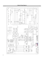
Page 28: ...27 Module Wiring Diagram...
Page 29: ...28 Module Panel Layout...
Page 31: ......
Page 32: ...1037 Old Salem Road Murfreesboro TN 37127 Phone 615 890 6985 info amgeo com www amgeo com...


