

9 10 11 1 2 3
8 7 6 5 4
Common
Open
Close
24˜VAC
˜˜#10
Supply
˜˜#3
˜˜˜#2
Supply
˜˜#1
Magnetic˜Contact˜Switch
11-Pin˜Base
Red˜Wire
Black˜Wire
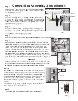
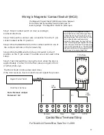
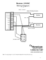
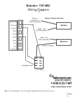
Step 1: Mount contact switch on door according to
enclosed directions.
Step 2: Remove the common wire connection from the 11 pin
socket, located at the #1 position.
Step 3: Wire the BLACK wire from the contact switch to one of
the common termials on the terminal strip.
Step 4: Wire the RED wire from the contct switch to the #1
position on the 11 pin socket. The white wire is not used in this
setup.
Step 5: Test limit switch by closing the door, when the door is
approximately 2 inches from the floor place an object in front
of either photo-eye.
The Door should continue down and close.
If the door reverses, check connections and repeat the process.
White˜Wire˜is˜Not˜Used
Control˜Box˜Terminal˜Strip
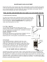
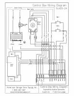
Wiring˜a˜Magnetic˜Contact˜Switch˜(MCS)
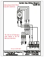
The˜purpose˜of˜the˜Magnetic˜Contact˜
Switch˜(MCS)˜is˜to˜block˜the˜signal˜from˜˜
auxiliary˜devices˜such˜as˜photo˜eyes˜or˜
reversing˜edges.˜˜When˜the˜door˜is˜in˜the˜
fully˜closed˜position˜and˜something˜
breaks˜the˜photo˜eyes,˜the˜door˜will˜not˜
open.˜˜Reversing˜edges˜require˜a˜shut-off˜
device˜to˜prevent˜the˜door˜from˜reopening˜
upon˜contact˜with˜the˜floor.˜˜The˜MCS˜will˜
also˜prevent˜the˜door˜from˜opening˜if˜the˜
photo˜eyes˜or˜reversing˜edge˜fails.
The˜Magnetic˜Contact˜Switch˜(MCS)˜wires˜inline˜between˜
the˜common˜and˜the˜auxiliary˜device˜(photo˜eyes˜or˜
reversing˜edge).˜˜The˜diagram˜is˜shown˜for˜photo˜eyes.
For˜SLA20-24˜Control˜Box,˜Date˜04-11-2019
1RWH5HPRYH-XPSHU
%HWZHHQ
.
23


