American Dynamics AD100 Installation Instructions Manual Download Page 6

6     Recorder Controller/Interface Installation Instructions

8000-1796-01, Rev. B

Note: 

With each successive module addressed,

additional time is required to find the module. The
search time increases by approximately 5 seconds
for each additional module. For example, when
looking for the fifteenth module, the search time
will be slightly longer than one minute

.

3.


When the dialog box message says “

Looking for

Module N+1

” press the Close button.

Mapping the Recorder Types

With the initial RIU window displayed on the PC
screen, the user must now list the recorder types used in
the system in the window’s left-most “Recorder Types”
column.

The RIU utility comes loaded with four standard VCR
types. If any or all of the four default models are
chosen, it is not necessary to learn IR commands. If a
new recorder type is entered in the system, the Learning
IR Commands procedures that are discussed in the next
section (

Mapping Non-Default Recorder Types

) have to

be implemented.

To map any of the default types, implement the
following procedure:
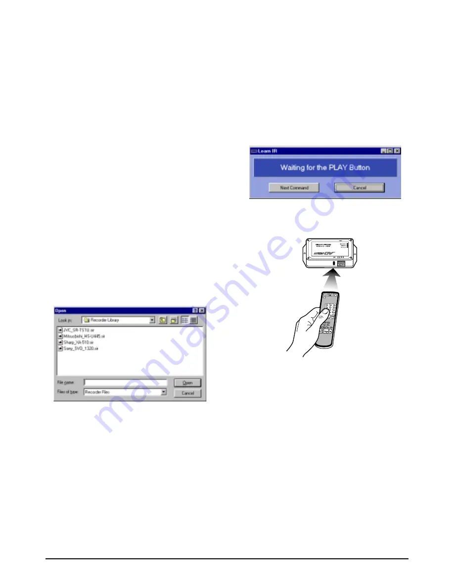
1.


Click in any row of the left-most 

Recorder Types

column. The 

Recorder Library

 dialog box appears.

2.


Select the appropriate file and press the Open
button. The file name appears in the selected row of
the left-most 

Recorder Types

 column.

3.


Repeat steps 1 and 2 for each default recorder type
in the system.

Mapping Non-Default Recorder Types

If the system utilizes recorder types other than those
provided as RIU default models, the user must map the
non-default model(s) and “learn” the IR command set
appropriate to the model(s).
To map additional recorder types and learn the
appropriate IR command sets, perform the following
steps:

1.


Select 

Functions/Learn IR Commands

. The

Recorder Library dialog box again appears (see
illustration under 

Mapping the Recorder Types

).

2.


Type an appropriate file name (typically based on
the make and model of the recorder being used) and
save the file. The file will automatically be saved
with the extension “.sir”. Another dialog box
appears:

3.


Aim the remote control device for the chosen
recorder at the built-in IR receive sensor adjacent
to the communication terminals on the AD100XA.

4.


Press the remote control’s PLAY button. The
PLAY dialog box will indicate the signal has been
received, and will prompt for the next remote
command (“RECORD”).

5.


Repeat steps 3 and 4 for each of the remote
commands indicated on the dialog box. The
complete set of commands appears in the following
sequence: “play”, “record”, “rewind”, “fast
forward”, “stop”, “eject”, and “pause”. If the
particular remote control device being used does
not include the button that is “waiting” in the dialog
box, simply press the “Next Command” button to
advance to the next prompt

6.


When all commands have been received, a progress
bar appears next to the “TX” and “RX” buttons in
the upper right-hand portion of the RIU window.
While the transmit and receive buttons flash, the
progress bar advances from zero to 100 percent.

Summary of Contents for AD100

Page 1: ...ill also support recorder control Particular systems developed before AD1024 can support recorder control with appropriate upgrade equipment see the table on page 8 for details The AD Recorder Controller interface is available for both 120 VAC and 230 VAC applications Equipment Provided see Drawing 1 Page 3 Part Qty Part No Recorder Controller 120 VAC 1 AD100XA Recorder Controller 230 VAC 1 AD100X...

Page 2: ...When used in concert with the recorder controller and utility software the IR interface module can control any recorder having IR capability Up to 2048 IR video recorders can be controlled on the network Each IR interface module is supplied with a transformer to power the unit RIU Recorder Interface Utility In order to implement the programming of the IR Interface Modules each Recorder Controller ...

Page 3: ...quipment AD100 Series System Drawings Drawing 1 System Equipment AD100XA Front View This connector not used AD100XA Rear View AD100IR16 Front View AD100IR16 Rear View Modular Cable with DB9F DB9M Adaptors AD100IRE Emitter Cable 120 VAC Transformer 230 VAC Transformer Opening for Addressing Switch ...

Page 4: ...called riu exe resides in the RIU folder 4 A new folder called Recorder Library resides in the C drive 5 Four VCR files are installed in the Recorder Library folder The filenames refer to four standard VCRs denoted by brand name and model number Launching the Application On the Windows desktop click the following sequence 1 Start 2 Programs 3 American Dynamics 4 Recorder Installation Utility The i...

Page 5: ...ler Interface Installation Instructions 5 Drawing 2 Daisy Chain Configuration Drawing 3 AD100 Interface w PC Video Recorders AD100 Series System Drawings Drawing 2 Daisy Chain Configuration Drawing 3 AD100 Interface w PC Video Recorders ...

Page 6: ...order Types If the system utilizes recorder types other than those provided as RIU default models the user must map the non default model s and learn the IR command set appropriate to the model s To map additional recorder types and learn the appropriate IR command sets perform the following steps 1 Select Functions Learn IR Commands The Recorder Library dialog box again appears see illustration u...

Page 7: ...he right most Recorder Types column in the row adjacent to the appropriate output number click and drag to assign the selected recorder type to multiple outputs 4 Click on the arrow in the center of the initial RIU window The selected recorder type will appear to the right of the appropriate output s Assigning Recorder Numbers to Outputs 1 To assign a recorder number click in the Recorder cell to ...

Page 8: ...the DB9F adaptor from the modular cable Connect the RJ 45 connector to the Peripheral Interface Port PIP of the AD1024 CPU Settings for the PIP are as follows Baud rate 9600 Data Bits 8 Stop Bits 1 Parity None 2 Using the AD2088 keyboard call up each of the system video recorder and test each of the recorder command functions see Drawing 4 page 9 Notes on Controller Setup Functions When the Functi...

Page 9: ...8000 1796 01 Rev B Recorder Controller Interface Installation Instructions 9 Drawing 4 AD100 Interface w AD1024 System Drawing 4 AD100 Interface w AD1024 System ...

Page 10: ... in Height 1 38 in AD100IR16 1 Length 5 50 in Width 3 25 in Height 1 38 in Environmental Specifications Operating Temp 5 C to 40 C 40 F to 104 F Humidity 95 non condensing Storage Temp 40 C to 70 C 40 F to 155 F Approvals UL UL listed transformer with device CSA CSA certified transformer provided w device CE CE marked transformer provided with device Warranty Disclaimer Sensormatic Electronics Cor...

Page 11: ...ntonio Cork Ireland Aguadilla P R 00690 Declares that the product s listed below Name Type AD100 Series Recorder Interface Modules Model Numbers AD100XA 1 AD100IR16 1 comply with the EMC Standards EN55022 Class B EN50082 1 and also comply with the following safety standard EN60950 Each module is provided with an external power supply Additional information These products herein comply with the req...

Page 12: ...12 Recorder Controller Interface Installation Instructions 8000 1796 01 Rev B Sensormatic Video Systems Division 1 Blue Hill Plaza Pearl River New York 10965 914 624 7600 ...

Reviews: