


High-Level Data Link Control (HDLC)
15-10
Am186™CC/CH/CU Microcontrollers User’s Manual
■
Remote Loopback Mode: To enable Remote Loopback mode, set the LOOPR bit in
the HxCON register to 1. Remote Loopback disables the transmitter and echoes the
data received at the serial input out to the serial output. The receiver operates normally
in this mode.
■
Local Loopback Mode: To enable Local Loopback mode, set the LOOPL bit in the
HxCON register to 1. Local Loopback mode disconnects the serial input and connects
the serial output to the receiver input. The serial output can operate in three-state, open
drain, or totem pole mode.
■
CRC Type: The algorithm for CRC generation and checking can be CRC-CCIT, CRC-16,
or CRC-32. Specify the CRC type in the CRCTYPE field of the HxCON register.
■
Time Slot Assigner (TSA): Each HDLC channel is tightly coupled with a TSA, which
can operate in either multiplexed or nonmultiplexed (pass-through) mode. In multiplexed
mode, the TXCLK input becomes the synchronization input and the TSA connects the
receive clock to the transmit clock. In multiplexed mode, the TSA controller determines
when to enable and disable the HDLC clock. It also allows the user to reduce the number
of bits transmitted in a single 8-bit time slot. This reduction allows the transmission of
data from 64 Kbit/s down to 8 Kbit/s in 8 Kbit/s decrements. This feature allows the HDLC
channel to be used for LAP-D and reduced data mode LAP-B transmissions such as
56 Kbit/s.
15.5.4
HDLC Transmitter
The transmitter functions include:
■
Opening flag transmission
■
Data transparency (via zero insertion)
■
Generation and transmission of the CRC frame-check-sequence characters (if enabled)
■
Transmission of the closing flag.
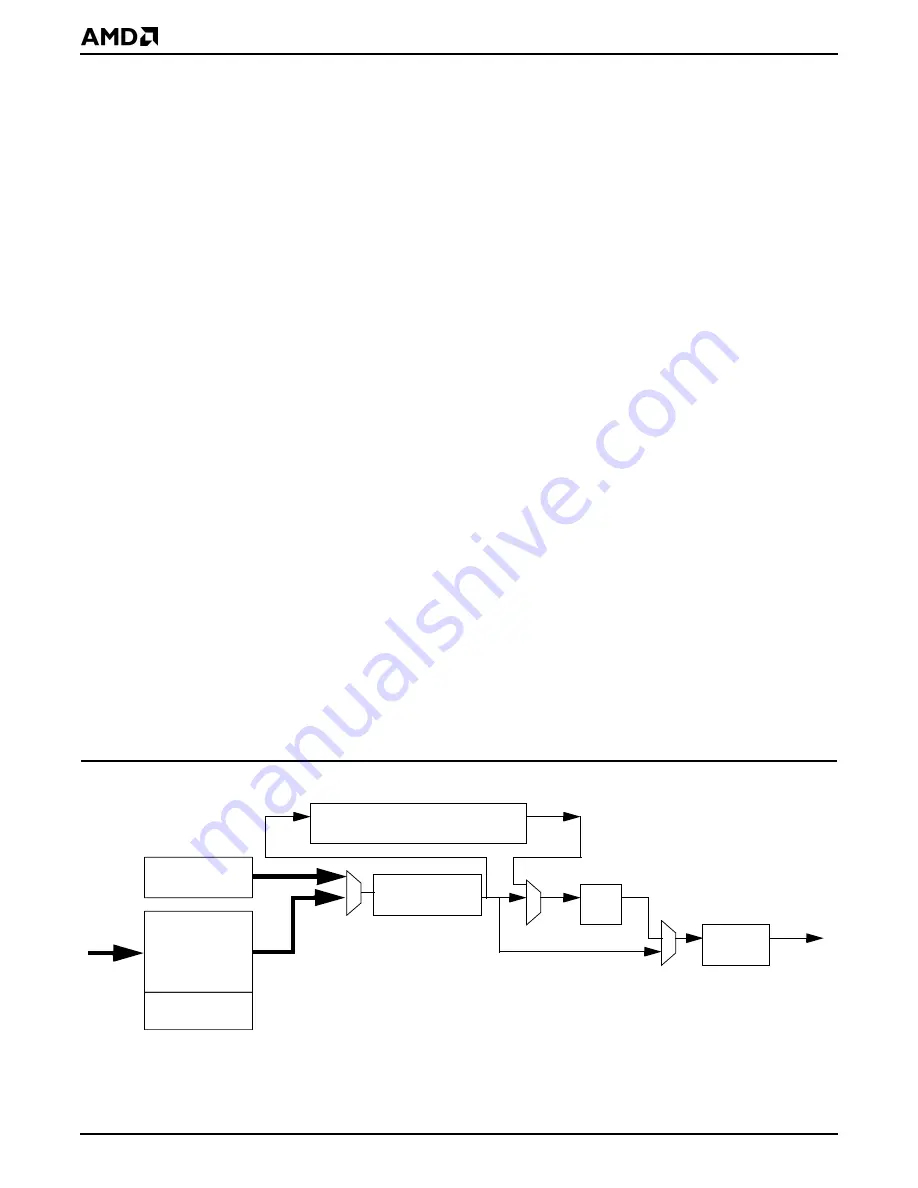
Figure 15-3 illustrates the block diagram for the transmitter.
Note: The HDLC transmitter requires at least one byte of data surrounded by flags: the
start flag, one byte of data, and the end flag. A 2-byte CRC with no data also constitutes a
valid transmission. The HDLC receiver can receive only frames two bytes or longer.
Figure 15-3
HDLC Transmitter Block Diagram
Flag/Abort
Generator
CRC Generator (16- or 32-bit)
Zero
Insert
Transmit
Transparent Mode Path
Parallel-to-Serial
Shift Register
FIFO
Serial
From
CPU
output
NRZ/NRZI
Encoder
End-of-Frame
Tag
Summary of Contents for Am186 CC
Page 1: ...Am186 CC CH CU Microcontrollers User s Manual Order 21914B...
Page 4: ...iv Am186 CC CH CU Microcontrollers User s Manual...
Page 18: ...Table of Contents xviii Am186 CC CH CU Microcontrollers User s Manual...
Page 24: ...Introduction xxiv Am186 CC CH CU Microcontrollers User s Manual...
Page 40: ...Architectural Overview 1 16 Am186 CC CH CU Microcontrollers User s Manual...
Page 86: ...System Overview 3 36 Am186 CC CH CU Microcontrollers User s Manual...
Page 92: ...Emulator Support 4 6 Am186 CC CH CU Microcontrollers User s Manual...
Page 112: ...DRAM Controller 6 8 Am186 CC CH CU Microcontrollers User s Manual...
Page 134: ...Interrupts 7 22 Am186 CC CH CU Microcontrollers User s Manual...
Page 186: ...Programmable I O Signals 9 8 Am186 CC CH CU Microcontrollers User s Manual...
Page 200: ...Watchdog Timer 11 6 Am186 CC CH CU Microcontrollers User s Manual...
Page 232: ...Asynchronous Serial Ports UARTs 13 24 Am186 CC CH CU Microcontrollers User s Manual...
Page 242: ...Synchronous Serial Port SSI 14 10 Am186 CC CH CU Microcontrollers User s Manual...
Page 264: ...High Level Data Link Control HDLC 15 22 Am186 CC CH CU Microcontrollers User s Manual...
Page 332: ...Universal Serial Bus USB 18 34 Am186 CC CH CU Microcontrollers User s Manual...
Page 348: ...Register Summary A 16 Am186 CC CH CU Microcontrollers User s Manual...
Page 376: ...Index Index 18 Am186 CC CH CU Microcontrollers User s Manual...


