background image


37  


5.3.2.7 UPnP 

UPnP stands for Universal Plug and Play, and it is a protocol used to easily connect devices to the internet. In the 

case of this camera, it allows the camera to connect to the router in an easy manner to quickly allow for remote 
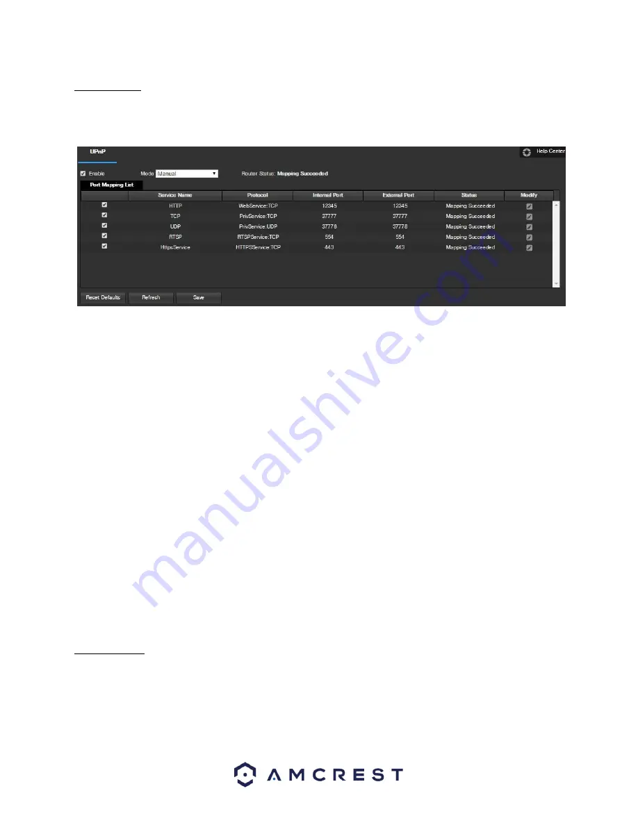
access. Below is a screenshot of the UPnP settings screen:  


Below is an explanation of fields on the UPnP settings screen:  
 

• 

Enable

: This checkbox allows the user to enable the UPnP function.  

• 

Router State

: This field shows the UPnP status and has two options:  

o


Unknown

: This means that UPnP mapping has failed.  

o


Successful

: This means that UPnP mapping has succeeded.  

• 

Port Mapping List

: This table is used to show how the ports for each protocol listed below have been remapped by 

the UPnP protocol.   

o


The first column shows the checkboxes to enable the corresponding service on the table.  

o


The second column shows the name of the services. To edit this, double click on the service line item.  

o


The third column shows the name of the protocol used by that service. To edit this, click the pencil button in the 
modify column for that line item.  

o


The fourth column shows the Internal Port used by that service to establish communication from the router to the 
camera. To edit this, click the pencil button in the modify column for that line item.  

o


The fifth column shows the External Port used by that service to establish communication from the router to the 
internet. To edit this, click the pencil button in the modify column for that line item.  

o


The sixth column shows the status of the protocol. If the protocol was mapped successfully, this field will say 

“Mapping Succeeded”. 


o


The seventh column allows the user to open a dialog box and edit the service’s information. 


To see how to setup the camera for remote access, see section 4.7. 
  
To reset to default settings, click the Reset Defaults button. To refresh the page, click the Refresh button. To save 

the settings, click the Save button.  


5.3.2.8 SNMP  


SNMP stands for Simple Network Management Protocol. This protocol is used to provide a basic framework in 

order to allow connection between various network devices. Below is a screenshot of the SNMP settings screen:  

Summary of Contents for IP3M-HX2B

Page 1: ...1 Amcrest IP3M HX2W IP3M HX2B 3MP Dual Band WiFi Hex Camera User Manual Version 2 0 2 Revised December 14th 2018...

Page 2: ...s 9 4 2 1 Setting up your camera for the first time 9 4 2 2 Accessing your camera using multiple mobile devices 9 4 2 3 Configuring advanced settings on your camera 9 4 2 4 Using Amcrest Cloud for rem...

Page 3: ...2 5 3 Setup 24 5 3 1 Camera 25 5 3 2 Network 31 5 3 3 Event 41 5 3 4 Storage 51 5 3 5 System 56 5 5 Alarm 61 6 FAQs Troubleshooting 62 Glossary of Terms 64 FCC Statement 65 Appendix A Toxic or Hazardo...

Page 4: ...st camera secure and prevent unauthorized access please make sure to follow the steps below Always make sure that your camera has the latest firmware as listed on www amcrest com firmware subscribe Ne...

Page 5: ...ntact the retailer that you purchased from or Amcrest directly if anything is broken or missing in the package 1 Features and Specifications 1 1 Overview Amcrest cameras are an excellent digital surve...

Page 6: ...tocol Support The camera is UPnP compatible and includes functionality for use with PPPoE DDNS and other protocols to allow remote and local connection with a large variety of network hardware Note Th...

Page 7: ...or is connecting to the network Red light is solid and steady The device failed to connect to the network Green Light is solid and steady The device is connected to the network and is functioning norm...

Page 8: ...ent can support at least 3 times the weight of the camera 4 Camera Access Setup This section of the guide will provide the user with information on how to setup access to the camera through any of the...

Page 9: ...ou to access recorded footage from any device We offer 4 hours of free storage for your first camera Please follow the instructions as outlined on section 4 5 Amcrest Cloud setup to sign up for our Am...

Page 10: ...your camera is recommended To add your camera onto the Amcrest Cloud app follow these steps 1 Download and open the Amcrest Cloud app from the App Store or Play Store Note Connect your mobile device t...

Page 11: ...word for your camera The password must be between 8 to 32 characters long and contain only letters and numbers When you have finished setting the password for your camera enter the password again in t...

Page 12: ...onfirmed tap Finish Note For Android 8 0 and above users you will have to enable location permissions to be able to scan for your WiFi network For more information about the Amcrest Cloud app and its...

Page 13: ...WiFi device 1 2 Tap on Add Device to add a new device to your app 3 Tap on WiFi Camera 2 4 Select your connection type in this case select the left tab Set Up A New Camera On WiFi or Connect New Devic...

Page 14: ...a Tap Next to continue 5 7 Scan the QR code on the back side bottom of the camera or manually enter the camera s serial number into the Enter camera S N serial number field Press Next to continue 6 8...

Page 15: ...ocate an SSID visit amcrest com androidP 7 11 The app will prompt you to change the password for your camera Enter a password between 8 and 32 characters and confirm the password Press OK to continue...

Page 16: ...p Access your camera and all its features and settings on your local network using Internet Explorer Firefox or Safari on Windows or Mac This method of accessing the camera s interface is necessary to...

Page 17: ...p video tutorials available at http www amcrest com videos 4 5 Amcrest Cloud Desktop Setup Amcrest cameras can sync with Amcrest Cloud a service that stores recorded video streams to enable long term...

Page 18: ...s web interface open the main menu then go to Setup Network 2 Using the left hand menu go to the Connection menu and write down the HTTP port It is recommended to ensure the port number is at least 5...

Page 19: ...Setup Network 2 Open the TCP IP settings screen 3 By default the camera has the mode set to DHCP Ensure that DHCP is selected The IP Address Subnet Mask Default Gateway Preferred DNS and Alternate DNS...

Page 20: ...number from step 10 on to the end For example if the DDNS domain name is http abc123456789 AmcrestDDNS com and your HTTP Port is 33333 the URL would be http abc123456789 AmcrestDDNS com 33333 23 Enter...

Page 21: ...ation Digital Zoom Click this button to activate the zone selection function This allows the user to use the mouse to select a zone to zoom in on Snapshot Click this button to take a screenshot of the...

Page 22: ...ull screen mode Double click the mouse or click the ESC button to exit full screen mode Width Height Ratio This button allows the user to change the width height ratio for the live feed The options ar...

Page 23: ...ic date range From here the user can download these videos to their PC 5 Trim Panel This panel allows the user to trim playback video for download By specifying time stamps the user can trim down 6 Re...

Page 24: ...etup tab There are 3 main sections to note in the Setup tab 1 Menu Bar The menu bar is composed of menu sections which when clicked display any menu items that fall under their category 2 Menu Items T...

Page 25: ...creenshot that shows the Configuration tab in the Configuration menu item Below is an explanation for each of the fields on the Configuration tab in the Configuration menu item Profile This dropdown b...

Page 26: ...tional option to specify a gain range appears below this box When low motion blur is selected an additional option to specify shutter speed appears below this box When manual is selected additional op...

Page 27: ...es for each Full Time means that the system sticks to one profile the entire time it is running Schedule allows the user to dictate which times of the day are designated for the day profile and the ni...

Page 28: ...rate selected Bit Rate This dropdown box allows the user to select a bit rate Frame Interval This field allows the user to set the P frame amount between two I frames The value ranges from 1 to 150 s...

Page 29: ...of the boxes in the live view window and position or resize it as needed To remove a box click on it then click the delete button To remove all privacy filter boxes click the remove all button For Ch...

Page 30: ...yback snapshots to Click the Browse button to select a different destination folder The Playback Download field allows the user to select where to save playback video downloads to Click the Browse but...

Page 31: ...e user to select the microphone volume The value ranges from 0 to 100 The default value is 50 Speaker Volume This slider allows the user to select the speaker volume The value ranges from 0 to 100 The...

Page 32: ...he camera s MAC address which is unique to this device This number is readonly and is used to access a local area network LAN IP Version This dropdown allows the user to select the IP version The two...

Page 33: ...a screenshot of the Connection settings tab Below is an explanation of the fields on the Connection settings tab Max Connections This field allows the user to specify the maximum amount of users that...

Page 34: ...he camera maintain a persistent address despite changes in location or configuration What this means is that even when the camera is restarted moved or reconfigured it can keep the same IP address thu...

Page 35: ...kbox allows the user to enable the IP Filter feature for trusted sites Add IP MAC This button opens a popup that allows the user to add IP or MAC addresses to the trusted site list Note When accessing...

Page 36: ...that are available o SSL Secure Socket Layer o TLS Transport Layer Security Subject This field allows the user to define the subject line of the email that is sent to the receivers Recipients This fie...

Page 37: ...ocol used by that service To edit this click the pencil button in the modify column for that line item o The fourth column shows the Internal Port used by that service to establish communication from...

Page 38: ...hould not be the same as the SNMP port To reset to default settings click the Reset Defaults button To refresh the page click the Refresh button To save the settings click the Save button 5 3 2 9 Bonj...

Page 39: ...o save the settings click the Save button 5 3 2 11 WiFi The WiFi menu item has two tabs WiFi and WPS 5 3 2 11 1 WiFi The WiFi feature on this camera allows it to connect to a network wirelessly The IP...

Page 40: ...n To refresh the page click the Refresh button 5 3 2 12 802 1x 802 1x is an authentication method for connecting to a network Below is a screenshot of the 802 1x screen To enable 802 1x click the chec...

Page 41: ...allows the user to open the WiFi MultiMedia WMM options To reset to default settings click the Reset Defaults button To refresh the page click the Refresh button To save the settings click the Save bu...

Page 42: ...e from 5 to 600 seconds This time value controls how long the alarm signal lasts Based on motion detection a buzzer can go off a snapshot can be taken or the camera can begin recording o For example i...

Page 43: ...ion detection zones will not go into effect Clicking the cancel button to leave the motion detection zone and will not save the zone setup Record This checkbox allows the user to enable the camera to...

Page 44: ...s field specifies in seconds how long the delay between alarm activation and recording should be Relay Out This checkbox allows the user to enable the camera to trigger a connected alarm connected to...

Page 45: ...e This checkbox enables intensity change for the camera audio Sensitivity is the amount of change required to increase the audio detected by a percentage The lower the sensitivity the more audio varia...

Page 46: ...new alarm since the anti dither time has expired Record This checkbox allows the user to enable the camera to record video when an audio detection alarm is triggered Record Delay his field specifies i...

Page 47: ...pshot record channel functions will begin another 10 seconds while the screen prompt alarm upload email will not be activated again After 10 seconds if system detects another alarm signal it can gener...

Page 48: ...Card SD Card Error and Capacity Warning Enable This checkbox enables the SD Card abnormality trigger for the camera Relay Out This checkbox allows the user to enable the camera to trigger an alarm whe...

Page 49: ...r for the camera Record This checkbox allows the user to enable the camera to record video when a network abnormality is detected Record Delay This field specifies in seconds how long the delay betwee...

Page 50: ...failed login attempts must be attempted in order to trigger an Illegal Access abnormality event Relay Out This checkbox allows the user to enable the camera to trigger an alarm when illegal access is...

Page 51: ...the camera captures all footage for the specified time period General recording is represented by the color green o Motion Motion Detection recording means that the camera captures only footage when t...

Page 52: ...ots when the motion detection alarm is activated Motion recording is represented by the color yellow o Alarm Alarm means that the camera only takes snapshots when an alarm is activated Alarm recording...

Page 53: ...ngs o Record This checkbox is referring to video recording o Snapshot This checkbox is referring to snapshot recording Calendar This calendar allows the user to select days to designate as holidays On...

Page 54: ...k the Reset Defaults button To refresh the page click the Refresh button To save the settings click the Save button 5 3 4 2 2 SD Card This tab is where the user can change SD card settings Below is a...

Page 55: ...llows the user to specify a remote directory on the FTP to send the recorded media to Emergency Store on SD Card This checkbox allows the camera to store recorded media on the SD card in case the FTP...

Page 56: ...the camera should do when the disk is full There are 2 options Overwrite or Stop Record Mode This set of radio buttons allows the user to designate the recording mode The options are Auto Manual and O...

Page 57: ...utton 5 3 5 1 1 Date Time This tab is where the user can configure the date and time settings for the camera Below is a screenshot of the Date Time tab Below is an explanation of the fields on the Dat...

Page 58: ...age Users This menu allows the user to change the user accounts on the camera By default the camera only has the admin account which has all rights authorities Additional accounts can be created on th...

Page 59: ...n To export settings click the Export button 5 3 5 5 Auto Maintain This screen allows the user to set auto maintenance settings for the camera Below is a screenshot of the Auto Maintain screen Below i...

Page 60: ...camera s software versions as well as other information Below is a screenshot of the camera s version screen On this screen software version web interface version and ONVIF version are displayed Also...

Page 61: ...he checkboxes allow the user to narrow down which alarms they want to see in the alarm log Clicking the checkbox next to Prompt will cause the system to pop up a dialog box anytime an alarm is trigger...

Page 62: ...a few possible reasons why this may be occurring The camera is not compatible with the monitor The camera color or brightness settings are not correctly configured 5 Local Recordings are not searchabl...

Page 63: ...connection errors Web access may be setup incorrectly The username or password may be incorrect 12 Web Access live view is only displaying a static picture Both live playback and recorded playback are...

Page 64: ...e routing table and when the default gateway is not available Anti Dither This time value controls how long the alarm signal lasts The values in this field can range from 5 to 600 seconds Based on mot...

Page 65: ...ach in order to trigger an alarm UPnP UPnP stands for Universal Plug and Play and it is a protocol used to easily connect devices to the internet Video Tamper Video Tamper refers to any major changes...

Page 66: ...st 20 cm from all persons and must not be co located or operating in conjunction with any other antenna or transmitter End users and installers must be provided with antenna installation instructions...

Page 67: ...Note For detailed operational instructions please refer to the User Manual on the CD that was included in your purchase To view setup videos for many of the steps outlined in this guide go to http amc...

Reviews: