Amco Veba 809NG User Manual Download Page 75


USER


MANUAL 

809NG 
U

SE


B.44 

7845469-01  03/20 

subject to change without notice 


B.8 

USE UNDER SPECIAL SERVICE CONDITIONS 

Exceptionally, the crane can be operated even if the service conditions are not met, i.e when: 

-  the stabilizers feet are deployed on a soft surface 

-  the crane is operated in low-temperature environments 

-  the inclination angle of the crane's base exceeds the max. permitted value 

-  the crane is operated in-service wind 


In these events the entity of the unfavourable condition shall be estimated by skilled technicians. 

If more conditions should be present at the same time, all the respective derating factors shall be 

taken into account. 


B.8.1 

STABILIZERS ON SOFT SURFACE 

It could happen that the stabilizers must be deployed on a soft or unstable surface. In this event, if 

the user has not suitable support pads at disposal, a derating factor shall be applied to the max. 

working pressure, as follows: 
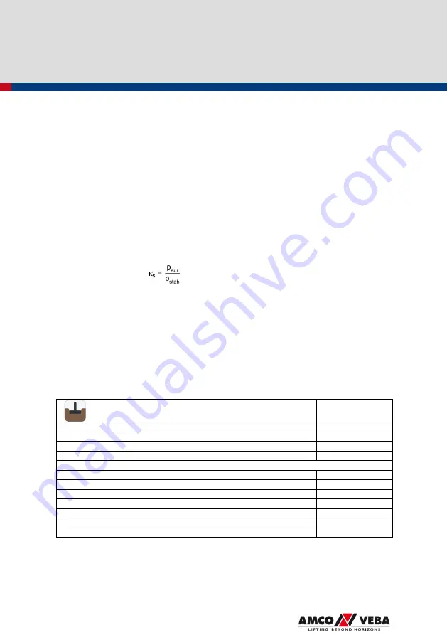
 

p

r

 = 

κ

s

 · p

max


with 


where: 

κ

s

  is the derating factor to apply if the support surface has insufficient bearing capacity 

p

r

  is the reduced pressure 

p

max

  is the max. working pressure under standard conditions 

p

sur

  is the effective bearing capacity of the surface supporting the stabilizers 

p

stab

  is the max. stabilizer pressure on the ground (see D.1) 


The following table shows typical values of bearing capacity (p

sur

) for  different soil types: these 

values are only indicative and can change depending on material, humidity, granulometry, hardness, 

inclination and other soil properties and conditions. 


SOIL TYPE 

BEARING CAPACITY 

MPa 

Natural, clearly virgin soils (mud, peat, marsh soil) 

Fill soil, not compacted 

0.0 ÷ 0.1 

Not coherent, but compact soils (fine and medium sand) 

0.15 

Coarse sand and gravel 

0.20 

Coherent soils: 


-  doughy 

-  soft 

0.04 

-  rigid 

0.1 

-  half-solid 

0.2 

-  solid 

0.4 

-  rock 

1.5 

-  solid rock 

3.0 

Summary of Contents for 809NG

Page 1: ...U US SE ER R M MA AN NU UA AL L 8 80 09 9N NG G ORIGINAL INSTRUCTIONS 7845469 01 03 20 subject to change without notice...

Page 2: ......

Page 3: ...NUAL B 1 B 1 PREMISE B 1 B 2 IDENTIFICATION B 2 B 3 DESCRIPTION AND DOCUMENTATION B 3 B 3 1 ENCLOSED DOCUMENTATION B 3 B 3 2 MARK B 3 B 3 3 SERVICE CONDITIONS B 4 B 3 4 MAIN COMPONENTS B 5 B 4 CONTROL...

Page 4: ...NK C 3 C 2 3 CLEANING THE CRANE C 3 C 2 4 SPECIAL PRECAUTIONS FOR CHROME PLATED SURFACES C 3 C 3 PLANNED AND EXTRAORDINARY MAINTENANCE C 4 C 4 TAKING THE CRANE OUT OF SERVICE C 4 C 4 1 DISASSEMBLY C 4...

Page 5: ...y goggles during maintenance tasks ear protection if the noise level in the operating position exceeds 80 dB A a dust mask in the presence of dusts a suitable mask in the presence of toxic fumes or po...

Page 6: ...BOOMS When the crane works with the booms in a near vertical alignment lifting moment is near zero the load limiting device could operate without the expected accuracy due to oscillations acceleratio...

Page 7: ...t not be left unsupervised put the load on a stable place before leaving the control station Do not slew the crane at max speed up to the end of stroke dead point but approach slowly Clear any snow or...

Page 8: ...er feet limb crushing in openings WARNINGS Cordon off the working area using barriers and warning signs before starting any operations with the crane Use special signals to warn others when crane move...

Page 9: ...ted in EN 349 and make sure all others do the same A 2 3 CUTTING HAZARD Residual hazard associated with movement of booms and connecting rods A residual cutting hazard exists for the upper limbs betwe...

Page 10: ...head on the boom during working operations Take great care not to bump against the suspended load The load must always be moved under safe conditions away from potential hazards and obstacles as speci...

Page 11: ...ey are too tight The crane is designed in such a way to prevent rubbing of hoses against moving parts However the installation configuration may cause hoses to come into contact with other moving part...

Page 12: ...amper with safety devices Stabilize the crane on firm ground WARNINGS Check that the parking brake is ON and the wheels are secured by using chocks Check that the stabiliser extensions are fully open...

Page 13: ...ilizer force When working on bridges the stabilizer feet must be placed at least one metre from the edge Make sure that the stabilizers are at a safe distance from ditches and steep slopes As a genera...

Page 14: ...y Inform the supervisor immediately of any loss of stability Routinely check correct functioning of the stabiliser legs Stop work immediately in the event of any faults and refer to an authorised assi...

Page 15: ...operating distance must be calculated taking into account the maximum crane outreach towards the lines and the maximum displacement of the lines D 7m The crane should only be used near live power lin...

Page 16: ...T HAZARDS A 4 1 BURNS These hazards are caused by Contact with hot hoses hot tanks and damage to hoses resulting in spurts of hot oil Use in explosive environments WARNINGS Do NOT touch any part of th...

Page 17: ...f the crane is used in environments with toxic fumes or substances WARNINGS FOR HYDRAULIC OIL AND INDUSTRIAL GREASE These substances must be handled with care in a ventilated environment Wear protecti...

Page 18: ...erator if the latter does not have a clear view of the entire working range of machine A 8 3 HUMAN ERROR WARNINGS Users must be able to read and understand the crane s documents and manuals Users must...

Page 19: ...lity impact falling loads sudden release of the lifting components and manual extensions accidents when moving the vehicle etc Incorrect folding of the crane can cause serious damage due to impact of...

Page 20: ...nents or accessories are protruding outside the profile of the vehicle e g prevent the hook from protruding 3 The LED warning light in cabin is green if present see B 6 5 1 2 3 In addition if the inte...

Page 21: ...using the crane Visually check that the hydraulic system is functioning correctly and that there are no fluid leaks between hoses and couplings Visually check the integrity of the machine structure a...

Page 22: ...ject to change without notice Visually check that the screws of the slewing cylinders all nuts and bolts in general are tightened properly Check that pins and screws used on the extensions and on othe...

Page 23: ...Unexpected or accidental movement of loads Unsuitable worn or unsafe lifting devices accessories Lifting of people Use during high winds Risk of damaging load support surfaces WARNINGS The following...

Page 24: ...ft truck releasing an excessive load on the hook lifting a floating load etc Movements very close to fixed walls trees etc and mobile cranes forklift trucks gantry cranes etc objects Lifting of people...

Page 25: ...cing the load on surfaces with unsuitable strength area or inclination Handling of loads at heights is strongly unrecommended the load could bump against the booms and oscillations of load and booms c...

Page 26: ...using a lift truck a crane or a bridge crane During transport by land and sea fix the crane or its container to the mean of transport body container hold etc Protect the crane from atmospheric agents...

Page 27: ...n retraction Impact hazard during extraction and retraction of extension Hazard from putting the body under excessive strain when lifting manual extensions WARNINGS The rated capacity of a manual exte...

Page 28: ...ocking pins of manual extensions Avoid boom positions causing the unpinned extension to move at high speeds Keep away from the extension s trajectory The user can manually lift the extension by himsel...

Page 29: ...d or to accidental disconnection of the lifting component Impact hazard for equipment against objects Structural damage hazard when pressing the load by lowering the crane boom Hazards due to maintena...

Page 30: ...th the tool Release the load as close to the ground or container as possible Do NOT overload the tool Take care that the load does not fall accidentally Do NOT operate the tool over areas where accide...

Page 31: ...d caused by drill operation Impact and cutting hazard during drill operation Structural damage and tipping hazard if the drill penetrates the ground but is unable to expel material WARNINGS Keep away...

Page 32: ...clean Dirt increases wear of the cylinders and pins Leaks of oil and other fluids are the main cause of accidents Follow the instructions in this manual Keep this manual in a safe place with the cran...

Page 33: ...operated extensions EX M stabilizers with extra spread and manually operated extensions EX H stabilizers with extra spread and hydraulically operated extensions SE H stabilizers with super spread and...

Page 34: ...uments completed and signed as necessary Declaration of EC conformity only for EC countries Certificate of origin Certificate of warranty User manual Spare parts catalogue The owner of the crane is re...

Page 35: ...x mean wind speed 34 km h Weather conditions to avoid Storm Sand storm Hydraulic oil temperature 10 C 80 C Max base inclination with respect to the horizontal 4 for duty S2 3 for duty S1 Bearing capac...

Page 36: ...99 MAIN COMPONENTS 1 Column 2 1st boom cylinder 3 1st boom 4 2nd boom cylinder 5 2nd boom 6 Extension cylinders 7 Hydraulic extensions 8 Stabilizer cylinder 9 Stabilizer extension 10 Oil tank 11 Slewi...

Page 37: ...USER MANUAL 809NG USE B 6 7845469 01 03 20 subject to change without notice B 4 CONTROLS B 4 1 CONTROL STATIONS NO RDC CRANE On main control valve side For NO CE only...

Page 38: ...USER MANUAL 809NG USE B 7 7845469 01 03 20 subject to change without notice NO RDC CRANE On the opposite control valve side For NO CE only...

Page 39: ...USER MANUAL 809NG USE B 8 7845469 01 03 20 subject to change without notice RDC CRANE EMERGENCY CONTROLS WITH DISPLAY On the main control valve side...

Page 40: ...USER MANUAL 809NG USE B 9 7845469 01 03 20 subject to change without notice RDC CRANE EMERGENCY CONTROLS WITHOUT DISPLAY On the main control valve side In case of work lights only ON OFF...

Page 41: ...USER MANUAL 809NG USE B 10 7845469 01 03 20 subject to change without notice RDC CRANE EMERGENCY CONTROLS On the opposite main control valve side...

Page 42: ...bled stabilizers enabled KEY SWITCH SELECTOR RDC NO TOP KS Stabilizers controls enabled Crane controls disabled Stabilizers controls disabled Emergency controls enabled Radio remote control disabled S...

Page 43: ...is working The MS1 lever is present only if the stabilizer extensions are hydraulically operated It is forbidden to place the stabilizer feet on the ground and to lift them off the ground by operating...

Page 44: ...unscrewed crane disabled stabilizers enabled RDC CRANE Break the seal sticker see figure below and turn the flow deviation lever under the cover Knob pulled lever turned clockwise crane enabled stabil...

Page 45: ...ract the hydraulic extensions immediately to stop the descent of the load B 5 2 EMERGENCY STOP BUTTON The emergency stop buttons are installed at the control positions of EC cranes In case of danger o...

Page 46: ...s reached the crane movements are blocked according to the figure below NO CE MOMENT LIMITER To remove the overload condition it is necessary to retract the hydraulic extensions until the lifting mome...

Page 47: ...eep raised the automatic lock and so allows to extend the outriggers FOR CRANES WITH MANUALLY OPERATED STABILIZER EXTENSIONS On both sides of the base two locking devices are installed an automatic lo...

Page 48: ...hine may cause damage to property and injury to people B 5 6 SLEWING LIMITERS The NO CE crane can be equipped with slewing limiter its purpose is to block the crane rotation toward the prohibited work...

Page 49: ...ental removal of the manual extension The plates allows the manual extension to slide freely between the fully retracted and fully extended position In order to remove the manual extension first thing...

Page 50: ...isual level indicators in order to check the amount of oil in the tank THERMOMETER CE cranes are fitted with a thermometer that shows the current oil temperature in degrees Celsius Yellow sector T 50...

Page 51: ...ure filter and clogging indicators B 6 2 LOAD INDICATORS SIGNAL LIGHT TOWER STANDARD FOR CE RDC CRANES The signal tower provides visual and audible warning signals to indicate the load level of crane...

Page 52: ...he pressure of the 1 boom cylinder Green sector 90 of lifting capacity is not reached Yellow sector 90 of lifting capacity is reached Red sector 100 of lifting capacity is reached B 6 3 LEVEL INDICATO...

Page 53: ...E IN CABIN The Road Safety Regulations set out the maximum dimensions of motor vehicles For this reason in CE area a visual audible warning device is installed in cabin this gives the driver permissio...

Page 54: ...ted on crane base and on additional stabilizers are ON when the crane is correctly stabilized ground can support the maximum pressure of stabilizer feet see D 1 all safety measures are properly execut...

Page 55: ...ocking device Lever 3 up the locking device 1 is engaged or ready to get engaged Lever 3 down the locking device 1 in disengaged Operating the crane is allowed only when the stabilizers are deployed c...

Page 56: ...k 1 rotate and lay the lock support 2 on the pin 3 Pull the suitable handle and extract completely the stabilizer extension till the semi automatic locking device 3 does stop the beam extension then s...

Page 57: ...the crane is fitted with turning stabilizer legs rotate downwards the leg up to the vertical position see B 7 5 5 Extend the cylinder till to place the foot on the ground without fully discharging the...

Page 58: ...CKING DEVICE OF STABILIZER EXTENSIONS 1 Automatic lock 2 Lock support Operating the crane is allowed only when the stabilizers are deployed correctly Always use the controls on the side on which you a...

Page 59: ...t to change without notice 2 Lower the automatic lock 1 rotate and lay the lock support 2 on the pin 3 By using the control lever below extract the stabilizer extension The yellow warning sign on exte...

Page 60: ...the crane is fitted with turning stabilizer legs rotate downwards the leg up to the vertical position see B 7 5 5 Extend the cylinder till to place the foot on the ground without fully discharging the...

Page 61: ...Locking device with lever Lever 1 perpendicular to extension axis down the locking device is engaged Lever 1 parallel to extension axis up the locking device is disengaged Execute the following proced...

Page 62: ...cking lever and rotate fully the leg downwards up to the vertical position the locking device engages automatically the lever turns clockwise and goes down If the locking device doesn t engage shake l...

Page 63: ...to change without notice B 7 6 OPENING PROCEDURE 1 If the crane is in folded position fully retract the 2nd boom cylinder articulation cylinder 2 Lift the 1st boom so that the 2nd boom can rotate free...

Page 64: ...compromised lift the loads from their center of gravity and make sure that they cannot move slide and rotate avoid sudden movements operate the control levers gently and gradually Do not swing the lo...

Page 65: ...SING PROCEDURE The operator should close the crane from the column side to avoid collisions with moving parts of the crane 1 Close the hydraulic extensions of the crane 2 Move the 1st boom so that the...

Page 66: ...Close the 2nd boom completely operating the control lever of the articulation cylinder 5 Lower the 1st boom until the recovery locks are in their seats Block the crane If for transport the crane is cl...

Page 67: ...support 3 Semi automatic locking device Lever 3 up the locking device 1 is engaged or ready to get engaged Lever 3 down the locking device 1 in disengaged The stabilizers can be closed exclusively aft...

Page 68: ...the leg up to its transport position see B 7 12 3 Turn the lever 3 downwards up to its vertical locking position the locking device is disengaged 4 Retract fully the stabilizer extension The automati...

Page 69: ...utomatic lock 2 Lock support The stabilizers can be closed exclusively after the booms are closed in transport position Always use the controls on the side on which you are operating the crane Execute...

Page 70: ...USER MANUAL 809NG USE B 39 7845469 01 03 20 subject to change without notice 3 Retract fully the stabilizer extension The automatic lock 1 engages automatically...

Page 71: ...1 Locking device with lever Lever 1 perpendicular to extension axis down the locking device is engaged Lever 1 parallel to extension axis up the locking device is disengaged Execute the following pro...

Page 72: ...ocking lever and rotate fully the leg upwards up to the vertical position the locking device engages automatically the lever turns clockwise and goes down If the locking device doesn t engage shake li...

Page 73: ...nt limiter see UM for RLC and 3XL 4XL INSTALLATION OF A MANUAL EXTENSION The procedure for a correct installation of a manual extension is the following 1 Put the extension onto a stable surface by me...

Page 74: ...equirements If the crane is equipped with an additional lifting tool intended to push to the ground bucket grab drill the rated capacities are not derated but the stress history class becomes irrevers...

Page 75: ...as not suitable support pads at disposal a derating factor shall be applied to the max working pressure as follows pr s pmax with where s is the derating factor to apply if the support surface has ins...

Page 76: ...ble below shows the value of T as the environmental temperature changes Environmental temperature C Derating factor T 20 Tenv 10 0 75 30 Tenv 20 0 50 40 Tenv 30 0 25 B 8 3 HIGH BASE INCLINATION The cr...

Page 77: ...g factor shall be applied to the max working pressure as follows pr w pmax where w is the derating factor to apply at mean wind speed of over 9 4 m s pr is the reduced pressure pmax is the max working...

Page 78: ...vane moves Gentle breeze 3 4 5 4 12 19 3 Leaves constant motion Light flag extended Moderate breeze 5 5 7 9 20 28 4 Raises dust and papers Small branches stir Fresh breeze 8 0 10 7 29 38 5 Small tree...

Page 79: ...esent Check the following before performing any maintenance operation The vehicle must be switched OFF and the brake applied The power supply to the crane must be switched OFF C 2 1 GREASING Grease th...

Page 80: ...hours 180 days Manual greasing of stabilizer extensions sliding surfaces Frequency of greasing 100 working hours 90 days Greasing under pressure of nipples Frequency of greasing 50 working hours 40 da...

Page 81: ...O H 32 IP HYDRUS 32 TOTAL AZOLLA ZS 32 10 C 35 C VG 46 98 18 16 13 BIOHYDRAULIC TMP FR 46 AGIP OSO 46 ESSO NUTO H 46 IP HYDRUS 46 TOTAL AZOLLA ZS 46 35 C 40 C VG 68 98 18 16 13 BIOHYDRAULIC TMP FR 68...

Page 82: ...ystem of vehicle 4 Disconnect the hydraulic connections to pump and tank Beware of escaping oil 5 Connect the crane to a lifting device remove the crane mounting bolts 6 Lift the crane and place it in...

Page 83: ...USER MANUAL 809NG TECHNICAL SHEET D 1 7845469 01 03 20 subject to change without notice D TECHNICAL SHEET...

Page 84: ...e base for the last extension hydraulic m 7 9 9 5 11 4 13 2 manual m N A 13 2 15 2 15 2 Weight of crane without stabilizers kg 1030 1110 1190 1260 Weight of stabilizers ST M kg 110 EX M kg 160 EX H kg...

Page 85: ...s the total weights including oil inside the cylinders fully retracted and considering oil tank empty kg Crane version Type of stabilizers 1S 2S 3S 4S ST M 1140 1220 1300 1370 EX M 1190 1270 1350 1420...

Page 86: ...2270 max 585 min 530 160 160 140 30 203 265 5 EXTRA FUNCTION 98 160 5 W W EXTRA FUNCTION 2070 2305 1S 2S 3S 4S W mm 840 840 840 840 W mm Compact 840 840 N A N A Slides 890 890 890 890 Hose reel N A N...

Page 87: ...66 604 5 641 5 277 5 327 1926 160 5 862 1086 B A 160 258 5 Ref Description Q ty Material Grade Size Tightening torque A Kit with 8 crane mounting bolts 8 42CrMo4 QT EN 10083 3 M20x1 5 L 900 250 Nm Kit...

Page 88: ...n types numbers ITN for cranes with standard dead point STOP toward swing bridge 1 STOP 2 3 STOP 4 STOP 5 STOP 6 STOP 7 STOP 8 STOP 9 10 11 Z3 12 13 STOP 14 15 STOP Z3 16 STOP OPPOSITE DEAD POINT STAN...

Page 89: ...USER MANUAL 809NG TECHNICAL SHEET D 7 7845469 01 03 20 subject to change without notice D 7 LIFTING HEIGHT CLOSE TO THE COLUMN 1000 H Version H mm 1S 1859 2S 1778 3S 1696 4S 1619...

Page 90: ...ubject to change without notice D 8 LOAD CHARTS FOR USE WITH HOOK TOOL 809NG 1S 0 2 4 6 8 2 4 6 8 10 kg kg 9 1 1510 2130 100 S2 S1 4 08 5 76 m kg 1510 2130 If an additional lifting tool is mounted the...

Page 91: ...809NG 2S 0 2 4 6 8 10 12 2 4 6 8 10 12 14 kg 10 7 kg 2020 1095 1415 16 710 600 12 6 14 4 100 m 4 08 7 45 5 76 m 4 08 9 41 11 21 kg 2020 1095 1415 S2 S1 Manual extensions optional these cannot lift add...

Page 92: ...G 3S kg 1920 990 1320 0 2 4 6 8 10 12 2 4 6 8 10 12 14 16 14 12 6 475 600 790 18 14 4 16 4 100 S2 S1 m 4 17 7 54 5 85 11 21 13 22 9 34 kg 1920 990 1320 790 Manual extensions optional these cannot lift...

Page 93: ...NG 4S 0 2 4 6 8 10 12 14 2 4 6 8 10 12 14 16 18 kg 1850 475 16 4 1230 14 4 920 710 600 m 4 24 7 61 9 41 11 21 13 22 5 92 kg 1850 1230 920 710 600 S2 S1 100 Manual extensions optional these cannot lift...

Page 94: ...12 7845469 01 03 20 subject to change without notice D 9 LOAD CHARTS FOR TI1 WINCH IN SINGLE LINE 809NG 1S TI1 SINGLE LINE 0 2 4 6 8 2 4 6 8 10 kg 1000 100 5 76 m S2 2 9m kg 1000 75 Minimum distance...

Page 95: ...13 7845469 01 03 20 subject to change without notice LOAD CHART FOR WINCH TI1 IN SINGLE LINE 809NG 2S TI1 SINGLE LINE 0 2 4 6 8 10 2 4 6 8 10 12 kg 1000 100 m 7 45 S2 kg 1000 75 2 9m Minimum distance...

Page 96: ...1 03 20 subject to change without notice LOAD CHART FOR WINCH TI1 IN SINGLE LINE 809NG 3S TI1 SINGLE LINE 990 0 2 4 6 8 10 12 2 4 6 8 10 12 14 790 100 7 54 9 34 kg 1000 75 2 9m kg 1000 m 7 46 S2 Minim...

Page 97: ...subject to change without notice LOAD CHART FOR WINCH TI1 IN SINGLE LINE 809NG 4S TI1 SINGLE LINE 0 2 4 6 8 10 12 14 2 4 6 8 10 12 14 16 kg 1000 920 710 600 m 7 61 9 41 11 21 7 09 100 S2 kg 1000 75 2...

Page 98: ...umn axis TL test load to be hooked to the last hydraulic extension X Y Z coordinates of center of gravity for whole crane folded in transport position EX H version in configuration with all hydraulic...

Page 99: ...change without notice D 11 HOOK DATA HOOK MOUNTED ON STANDARD BOOM VERSIONS 1S 2S 3S 4S DIMENSIONS 5 4 t L L W D L 134 88 19 42 289 5 50 50 TECHNICAL PROPERTIES Working load limit WLL 5400 kg Material...

Page 100: ...USER MANUAL 809NG TECHNICAL SHEET D 18 7845469 01 03 20 subject to change without notice D 12 LOAD ATTACHMENT ATTACHMENT FOR HOOK 56 24 25 R 30 55 25 75 45...

Page 101: ...e following operating conditions unloaded crane operated with a single control lever oil flow rate recommended for NO RDC crane ISO VG 46 oil at a temperature of 50 C MAX ALLOWABLE SINK RATE FOR THE L...

Page 102: ...ion temperature 48 C Weight 13 5 kg Capacity 4 For a crane without oil cooler performing a sequence of standard work cycles the difference in temperature between the oil and the environment is shown i...

Page 103: ...s 75 C after the following working times Tenv C w to exceed 75 C minutes 45 no limit 48 35 50 25 52 20 54 15 The graph below shows the temperature trend Toil with oil cooler when Tenv 45 C Notes The m...

Page 104: ...between column axis stab cylinder Fsg max force on stabilizer leg Check that Fs Rmax Rmax is given in the technical specifications of the additional stabilizers Xs In addition CE additional stabilize...

Page 105: ...5 755 93 100 3S 790 H605 250 285 250 375 505 84 100 4S 600 H604 200 195 200 300 405 83 100 Notes 1 The gross load is the load capacity of crane at maximum hydraulic outreach 2 The tool s load capacity...

Page 106: ...5 700 84 100 3S 790 H653 4 small 275 120 180 515 58 100 4S 600 H653 4 small 275 120 180 325 76 100 Notes 1 The gross load is the load capacity of crane at maximum hydraulic outreach 2 The tool s load...

Page 107: ...340 100 34 2S 1095 H634 0 25 170 4000 925 100 23 3S 790 H634 0 25 170 4000 620 100 16 4S 600 H634 0 25 170 4000 430 100 11 Notes 1 The gross load is the load capacity of crane at maximum hydraulic out...

Page 108: ...1245 100 78 2S 1095 H332 1330 265 1600 830 100 52 3S 790 H332 1330 265 1600 525 100 33 4S 600 H332 1330 265 1600 335 100 21 Notes 1 The gross load is the load capacity of crane at maximum hydraulic o...

Page 109: ...0 68 2S 1095 H415 2000 500 155 2000 940 100 47 3S 790 H415 1500 500 135 1500 655 100 44 4S 600 H415 1500 500 135 1500 465 100 31 Notes 1 The gross load is the load capacity of crane at maximum hydraul...

Page 110: ...NUAL 809NG ANNEXES E 1 7845469 01 03 20 subject to change without notice E ANNEXES E 1 HYDRAULIC SCHEMATICS STABILIZERS MANUALLY OPERATED EXTENSIONS T P A1 A1 A2 B2 set p LDC B2 1040041 Settings pset...

Page 111: ...7845469 01 03 20 subject to change without notice HYDRAULIC SCHEMATICS STABILIZERS HYDRAULICALLY OPERATED EXTENSIONS FIXED OR MANUALLY TURNING STABILIZER LEGS T P A1 A1 B1 A2 B2 A3 B3 A4 B4 set p LDC...

Page 112: ...3 7845469 01 03 20 subject to change without notice HYDRAULIC SCHEMATICS ADDITIONAL STABILIZERS MANUALLY OPERATED EXTENSIONS T P A1 A2 B2 set p B2 T P CRANE S STABILIZERS CONTROL VALVE CARRY OVER 104...

Page 113: ...1 03 20 subject to change without notice HYDRAULIC SCHEMATICS ADDITIONAL STABILIZERS HYDRAULICALLY OPERATED EXTENSIONS T P CRANE S STABILIZERS CONTROL VALVE CARRY OVER T P A1 A1 B1 A2 B2 A3 B3 A4 B4 s...

Page 114: ...thout notice HYDRAULIC SCHEMATICS CONTROL VALVES NO RDC NO CE B4 A4 B5 A5 A3 B3 A2 B2 A1 pmax pB3 pB5 pA5 pA2 pB2 T P M q 1 7 bar 25 1030192 Settings q 20 min pmax 310 bar pA2 200 bar pB2 200 bar pA3...

Page 115: ...without notice HYDRAULIC SCHEMATICS CONTROL VALVES NO RDC CE B4 A4 B5 A5 A3 B3 A2 B2 A1 pmax pB3 pB5 pA5 pA2 pB2 T P M q 1 7 bar 25 1030193 Settings q 20 min pmax 310 bar pA2 200 bar pB2 200 bar pA3 3...

Page 116: ...nge without notice HYDRAULIC SCHEMATICS SUPPLEMENTARY ACTIVATION ELEMENTS NO RDC pA6 pB6 B6 A6 pA7 pB7 B7 A7 T T pB6 pA6 B6 A6 1030194 Settings for winch Settings for rotor und bucket grab pA6 200 bar...

Page 117: ...ATICS CONTROL VALVE RDC NO CE Ls LsA LsB LsA LsB LsA LsB LsA LsB A2 B2 P M T pmax HPCO pA2 pB2 pA3 pB3 pA4 pB4 pA5 pB5 A3 B3 A4 B4 A5 B5 A1 q 6 bar 10 1 7 bar 25 1030198 Settings q 40 min pmax 310 bar...

Page 118: ...without notice HYDRAULIC SCHEMATICS SUPPLEMENTARY ACTIVATION ELEMENTS RDC NO CE LsA LsB LsA LsB LsA LsB A6 B6 Ls T A6 B6 A7 B7 Ls T 1030199 Settings for winch Settings for rotor und bucket grab pA6 20...

Page 119: ...EMATICS CONTROL VALVE RDC CE Ls LsA LsB LsA LsB LsA LsB LsA LsB A2 B2 P M T pmax HPCO pA2 pB2 pA3 pB3 pA4 pB4 pA5 pB5 A3 B3 A4 B4 A5 B5 A1 q 6 bar 10 1 7 bar 25 1030196 Settings q 40 min pmax 310 bar...

Page 120: ...e without notice HYDRAULIC SCHEMATICS SUPPLEMENTARY ACTIVATION ELEMENTS RDC CE LsA LsB LsA LsB LsA LsB A6 B6 Ls T A6 B6 A7 B7 Ls T 1030197 Settings for winch Settings for rotor und bucket grab pA6 200...

Page 121: ...HYDRAULIC SCHEMATICS CONTROL VALVE FOR LS VARIABLE DISPLACEMENT PUMP RDC CE Ls LsA LsB LsA LsB LsA LsB LsA LsB A2 B2 P M T pmax HPCO pA2 pB2 pA3 pB3 pA4 pB4 pA5 pB5 A3 B3 A4 B4 A5 B5 A1 6 bar 10 1 7...

Page 122: ...USER MANUAL 809NG ANNEXES E 13 7845469 01 03 20 subject to change without notice HYDRAULIC SCHEMATICS OIL COOLER OPTION P T 1030250...

Page 123: ...USER MANUAL 809NG ANNEXES E 14 7845469 01 03 20 subject to change without notice HYDRAULIC SCHEMATICS SLEWING SYSTEM A B V1 V2 C1 C2 pset 1050102 Rack stroke 625 mm Settings pset 190 bar...

Page 124: ...845469 01 03 20 subject to change without notice HYDRAULIC SCHEMATICS 1ST BOOM CYLINDER pset3 pset2 C1 C2 V2 V1 pset1 M A B 1050093 Settings pset1 355 bar for 1S pset1 350 bar for 2S pset1 335 bar for...

Page 125: ...845469 01 03 20 subject to change without notice HYDRAULIC SCHEMATICS 2ST BOOM CYLINDER pset1 pset2 A B V2 V1 C2 C1 M 1050119 Settings pset1 345 bar for 1S pset1 355 bar for 2S pset1 365 bar for 3S ps...

Page 126: ...SER MANUAL 809NG ANNEXES E 17 7845469 01 03 20 subject to change without notice HYDRAULIC SCHEMATICS EXTENSION CYLINDERS A B V1 V2 C1 C2 2 1 3 pset1 pset2 4 1050105 Settings pset1 210 bar pset2 430 ba...

Page 127: ...UAL 809NG ANNEXES E 18 7845469 01 03 20 subject to change without notice HYDRAULIC SCHEMATICS MOMENT LIMITER NO RDC NO CE I M Pil P RS T pset P A B A B A B A B A B 5 bar Option M 1060093 Settings pset...

Page 128: ...out notice E 2 ELECTRIC SCHEMATICS TECHNICAL DATA Supply voltage 12V 24V Max current absorbed by the electric system 10A Max current absorbed by the electric system with radio controlled stabilizers 1...

Page 129: ...USER MANUAL 809NG ANNEXES E 20 7845469 01 03 20 subject to change without notice ELECTRIC SCHEMATICS EMERGENCY STOP BUTTONS NO RDC NO CE OPTION _ Y 1010225...

Page 130: ...ELECTRIC SCHEMATICS TERMINAL BOX ELECTRIC SCHEMATIC WINCH DI WINCH PWR TWL DEV DANFOSS 30 31 15 ROT DI DIR A DIR B EV LCS PRESS CRANE PRESS JIB PWR RDC SERVICE RDC EMERG 1 EMERG 2 POWER SUPPLY KEY SW...

Page 131: ...INCH OUT GND 24V KEY SWITCH TWL WINCH DI PWR RDC SERVICE RADIO JIB PRESS CRANE PRESS EV LCS DIR B DIR A ROT DI DEV DANFOSS RELE DISP 0PTON RADIO OUT OPTION RADIO IN 13 14 15 16 17 18 19 20 21 22 23 24...

Page 132: ...WITH DANFOSS EV STAB EV DUMP ROT DI WITH HYDROCONTROL WITH DANFOSS WITH HIDROCONTROL FUSE 10 AMP 1 2 3 4 59 61 60 59 60 61 62 Q2 EMERG 1 TWL DEV 1 2 3 4 52 53 54 55 32 35 33 34 36 39 37 38 KEYSWITCH...

Page 133: ...ONNECTOR CONTROL VALVE cables 24V POWER cable 2 4 1 3 5 16 PROGR V1 V2 V3 V4 V5 V6 V7 V8 1 2 3 4 5 6 7 8 9 10 11 12 13 14 15 16 PIN 34 19 33 18 32 60 20 17 31 30 15 16 61 62 9 10 13 14 12 1 2 59 57 43...

Page 134: ...stabiliser legs during the stabilization of the crane On turning stabilizer legs Do NOT bang against the turning stabiliser legs during the stabilization of the crane On stabilizer legs NO CE Before s...

Page 135: ...l footwear Warning do NOT bang on the booms during opening and folding of the crane At RDC controls Seal sticker Do NOT use emergency controls under normal work conditions On column Read the operator...

Page 136: ...USER MANUAL 809NG ANNEXES E 27 7845469 01 03 20 subject to change without notice LOCATION OF SAFETY SIGNS...

Page 137: ...5 1387 1969 2305 Notes in case of connection Geomet bolt Untreated support or nut multiply the tabulated values by 0 85 in case of connection Geomet bolt Geomet nut multiply the tabulated values by 0...

Page 138: ...n temperature affect viscosity as the temperature increases viscosity decreases The following table shows the effect of temperature on oil viscosity STARTING AND OPERATING VISCOSITY RANGE STARTING AND...

Page 139: ...bridge is locked by means of a rotation locking device The swivel lock consists of a device equipped with locking pins that prevent the bridge rotation with respect to the base The swivel lock is scre...

Page 140: ...movement of the crane 1 No motive power 2 Emergency stop button on 3 Safety solenoid valve damaged 1 Check there is motive power 2 Disengage the emergency push button after checking there are no dange...

Page 141: ...l minutes in order to warm up the oil Vibrations in all movements when the oil is warm 1 Insufficient oil in the tank 2 Air inside hydraulic circuit 1 Add hydraulic oil 2 Operate the controls to fully...

Page 142: ...USER MANUAL 809NG ANNEXES E 33 7845469 01 03 20 subject to change without notice E 8 EC DECLARATION OF CONFORMITY...

Page 143: ......

Reviews: