20 Gear Drive, Plymouth Ind. Park, Terryville, CT 06786
Tel: (860) 585-1254 Fax: (860) 584-1973 http://www.amci.com
Output Data Format
5
67
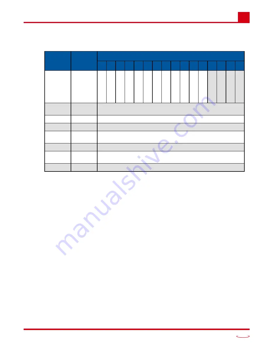
Command Block 8: Program Brake Monitor Parameters
This block allows you to program the brake monitor parameters. An explanation of the
func-
tion can be found starting on page 27.
Figure 5.11 Command Block 8
Command Word Bits
Bit 5:
Delete All Brake Monitor Data.
Setting this bit to ‘1’ will delete all of the parameter values associated
with the Brake Monitor and disable it.
Bit 8:
Program Brake Monitor Input.
If this bit is reset to ‘0’ the value in word 1 is ignored. If this bit is set
to ‘1’, the input designated in word 1 is used as the Brake Monitor Input.
Bit 9:
Program Complete Stop Count.
If this bit is reset to ‘0’ the value in word 2 is ignored. If this bit is
set to ‘1’, the Complete Set Count parameter is set to the value in word 2. The transducer is consid-
ered stopped when the change in position in 125 milliseconds is less than this programmed value.
The Complete Stop Count is always programmed with a resolution of 4,096 counts per turn.
Bit 10: Program Start Time Limit.
If this bit is reset to ‘0’ the value in word 3 is ignored. If this bit is set to
‘1’, word 3 sets the maximum time between the release of the brake and the start of transducer move-
ment that can occur without a fault indication.
Bit 11: Program Start Time Overrun Output.
If this bit is reset to ‘0’ the value in word 4 is ignored. If this bit
is set to ‘1’, word 4 sets the output that will switch from its inactive to active state when the starting
time exceeds the programmed Start Time Limit.
Bit 12: Program Stop Time Limit.
If this bit is reset to ‘0’ the value in word 5 is ignored. If this bit is set to
‘1’, word 5 sets the maximum time between the activation of the brake and the end of transducer
movement that can occur without a fault indication.
Bit 13: Program Start Time Overrun Output.
If this bit is reset to ‘0’ the value in word 6 is ignored. If this bit
is set to ‘1’, word 6 sets the output that will switch from its inactive to active state when the stopping
time exceeds the programmed Start Time Limit.
EtherNet/IP
Address
Modbus
Address
Bit Number
15
14
13
12
11
10
9
8
7
6
5
4
3
2
1
0
0
1024
T
ransmit Bi
t
0
Apply W
o
rd 6
Apply W
o
rd 5
Apply W
o
rd 4
Apply W
o
rd 3
Apply W
o
rd 2
Apply W
o
rd 1
0
0
Delete All
Clear Error
1
0
0
0
1
1025
Brake Monitor Input (Range of 0, 1 to 16)
If ‘0’, brake monitor function is disabled
2
1026
Complete Stop Count (Range of 0 to 255)
3
1027
Start Time Limit (Range of 0 to 32,767 milliseconds)
4
1028
Start Time Overrun Output (Range of 0, 1 to 16)
If ‘0’, no output is assigned
5
1029
Stop Time Limit (Range of 0 to 32,767 milliseconds)
6
1030
Stop Time Overrun Output (Range of 0, 1 to 16)
If ‘0’, no output is assigned
7 - 19
1031-1043
Not Used
Summary of Contents for ANS1 ANYNET-I/O
Page 1: ...MICRO CONTROLS INC ADVANCED U s e r M anual Manual 940 0A090...
Page 6: ...Table of Contents ADVANCED MICRO CONTROLS INC 6 Notes...
Page 26: ...Limit Switch Functionality ADVANCED MICRO CONTROLS INC 2 26 Notes...
Page 36: ...Additional Functionality ADVANCED MICRO CONTROLS INC 3 36 Notes...
Page 90: ...LEADERS IN ADVANCED CONTROL PRODUCTS ADVANCED MICRO CONTROLS INC...


