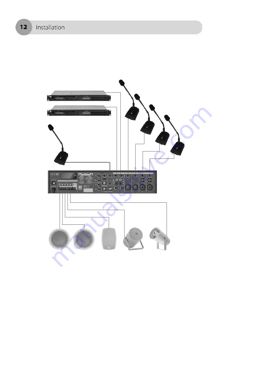
Typical input and output wiring diagram is shown in a figure below.
Page 1: ......
Page 2: ...rt Precautions 3 Before you start 5 Controls and connections Front panel 6 Rear panel 6 Installation Rack mounting 7 Wire connectors 8 Connections 10 Adjusting amplifier 14 Specifications Block diagra...
Page 3: ...st damage nor modify the power supply cord In addition avoid using the power cord close to heaters and don t place heavy object including the amplifier itself on the power cord as it may cause fire or...
Page 4: ...aterials into the ventilation slots of the amplifier for it may result fire or electric shock DO NOT open nor remove the amplifier cover to prevent fire or electric shock for there are high voltage co...
Page 5: ...warranty may be voided Connect this unit with matching system components described on the following pages Features MMA 60 MMA 120 and MMA 240 are comprehensive all in one mixer amplifier solutions for...
Page 6: ...nput channel volume controls 9 Power switch 5 Master volume controls Rear panel description 1 AC fuse 7 Signal input connectors 2 Expansion ports AMP IN PRE AMP OUT LINK IN LINK OUT 8 Remote microphon...
Page 7: ...units for efficient convection cooling There should be also left 2 inches space between unit sides and rack side walls and 4 inches from unit rear panel and back of the rack How to attach rack mount b...
Page 8: ...ment for appropriate wiring application RCA input connectors may also be used for unbalanced signal inputs Balanced line Balanced line Unbalanced line Unbalanced line TRS mono jack for unbalanced conn...
Page 9: ...the appropriate size wire based on the distance between amplifier and speaker The wire sizes are given for a 4 load NOTE Custom wiring should only be performed by qualified personnel CAUTION Never use...
Page 10: ...positive lead Impedance and output voltages ratios MMA 60 4 15 5V 10 25V 83 70V 165 100V MMA 120 4 22V 5 2 25V 42 70V 83 100V MMA 240 4 31V 2 6 25V 21 70V 42 100V NOTE The total speaker system impeda...
Page 11: ...Possible speaker connection types are shown in a figure below CAUTION Never use both the Low Z 4 and Hi Z 25V 70V and 100V terminals at the same time...
Page 12: ...Typical input and output wiring diagram is shown in a figure below...
Page 13: ...desired sound output NOTE Inserting a 1 4 TRS jack into AMP IN terminal disconnects internal power amplifier section from the mixer section Expanding MMA series MMA series mixer amplifier allows expan...
Page 14: ...changing jumper position on a T3 Priority This function allows talk over for MIC channel 1 and 2 While this function is activated all other input signals are muted Figure shows the priority switches a...
Page 15: ...IN Channel 6 input channel Tele paging function Priority signal from PBX station could be connected to MMA series mixer amplifier via TELE PAGING Phoenix connector This way public announcement could...
Page 16: ...Example application diagram is shown in a figure below...
Page 17: ...Block diagram...
Page 18: ...5Hz 250Hz 500Hz 1kHz 2kHz 4kHz 8kHz 12dB Signal to Noise Ratio at rated power output Better than 90dB Crosstalk at all control maximum 70dB at 1kHz Total Harmonic Distortion THD at 1kHz rated power Le...