


Doc No 700111 (06-15), Page 14
Note The vent terminal
should be installed so as
to be in the same atmospheric
pressure zone as the combustion
air inlet of the appliance.
Note the vent terminal must NOT
be installed below the fresh air
intake, and should have a
minimum separation distance of
36” from the air intake.
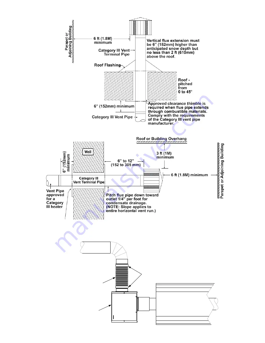
Approved clearance thimble is required when the flue pipe
extends through combustible materials. Follow the
requirements of the thimble and/or Category III vent pipe
manufacturer.
Approved Vent Cap
Figure 7.b Horizontal Venting (plan view shown).
Approved Vent Cap
Figure 7.a Vertical Venting.
Aluminum 4” (101mm) O.D. pipe.
Max length = 25’0” (7.62M) with 2
x 90° long radius bends.
4” (101mm) O.D. flexible duct
Burner
Clamps
Figure 7.c Fresh Air Ducted Intake.