


Product description
4
Product description
This section:
•
Provides a comprehensive overview of the machine structure.
•
Provides the names of the individual modules and controls.
Read this section when actually at the machine. This helps you to
understand the machine better.
4.1
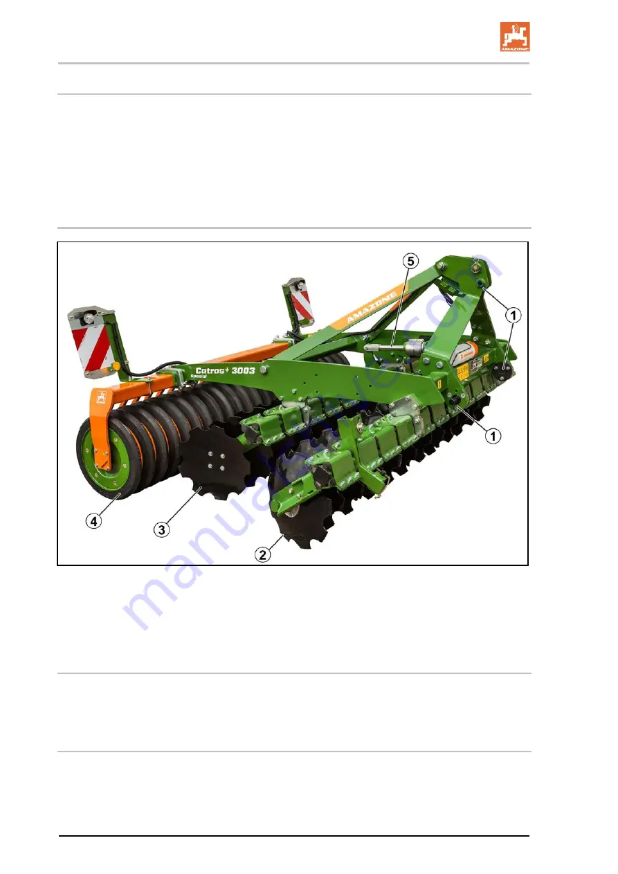
Overview of subassemblies
(1) Three-point attachment
(2) 1. disc row
(3) 2. disc row
(4) Trailing roller in various versions
(5) Setting the working depth
4.2
Safety and protection equipment
Transport safety bar for the rear harrow during road transport.
4.3
Supply lines between the tractor and the machine
Electric cable for lighting
26
Catros BAG0160.4 02.19
Summary of Contents for Catros 2503 Special
Page 70: ...G ...


