Amantii WM -FM -26-3623-BG Installation And Operation Instructions Manual Download Page 17


17 

REM OTE CONTROL OPERATION 


For  remot e  t o  funct ion  make  sure  t he  heat er  is  plugged  in  and  main  power  sw it ch  located  on  t he 

bott om left  hand side is at  posit ion I. 

When operat ing t he remot e make sure you point  t he remote t o t he cent re of t he fireplace and make 

sure each t ime you press t he butt on t he buzzer inside t he unit  w ill beep once. It  t akes some t ime for 

t he  receiver  t o  respond  t o  t he  t ransmitt er.  Do  not   PRESS  t he  butt ons  more  t han  once  w it hin  t wo 

seconds for correct  operat ion. 
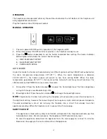
 

Power  on 

  butt on:  The  power-on  but t on  at   t op  left   corner  of  t he  remot e  is  t he  main  ON/ OFF 

power butt on. This w ill t urn off all t he funct ions and t he fireplace w ill be in st andby mode. 


DISPLAY  ON/ OFF  button

:


Sw it ching  t he  fireplace  flame  and  t ray  light   ON/ OFF.  It   has  funct ions  of 

set t ing memory. 

DISPLAY BLUE button

: Adjust  t he blue color bright ness of flame and t ray. 

DISPLAY YELLOW  button

: Adjust  t he yellow  color bright ness of flame and t ray. 

DISPLAY ORANGE button

: Adjust  t he orange color bright ness of flame and t ray. 

M OOD LIGHT ON/ OFF button

: Sw it ching t he mood light  ON/ OFF. 

ADJUST button

: Sw it ching t he color of t he mood light . 

FLASH button

: Sw it ches t he mood light  into flash mode, t his cycles t hrough all mood light  colors. 

HEATER ON/ OFF button

: Sw it ching t he heater ON/ OFF. It  has funct ions of set t ing memory. 

HIGHT button

: Press t he high butt on t o sw it ch t he heat er t o high heat  set t ing 1500W. 

LOW  button

: Press t he low  but t on t o sw it ch t he heat er t o low  heat  sett ing 750W. 

TEM P.  button

:  Press  t he  TEM P.  butt on  t o  sw it ch  t he  heat er  t o  AUTO  mode.  Under  t his  mode  t he 

heat er w ill operate in similar way as explained above for t he manual operat ion. 

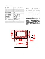
Summary of Contents for WM -FM -26-3623-BG

Page 1: ...INFORMATION WARNING If the information in these instructions are not followed exactly a fire or explosion may result causing property damage personal injury or loss of life Do not store or use gasoli...

Page 2: ...3 UNPACKING AND TESTING APPLIANCE 4 GROUNDING APPLIANCE 4 LOCATING THE FIREPLACE 4 WM FM 34 4423 BG 6 WM FM 48 5823 BG 7 WM FM 60 7023 BG 8 WM FM 72 8123 BG 9 WM FM 88 10023 BG 10 REMOVING FRONT GLASS...

Page 3: ...not insert or allow foreign objects to enter any ventilation or exhaust opening as this may cause an electric shock fire or damage to the heater 10 To prevent a possible fire do not block air intakes...

Page 4: ...is available To disconnect appliance turn controls to off then remove plug from outlet LOCATING THE FIREPLACE Plan where to locate and frame the fireplace This will save time and money later when you...

Page 5: ...pening Size 27 20 1 2 or 68 60 cm 52 cm BTU 4800 This appliance has been tested in accordance with the UL Standard 2021 for fixed and location dedicated electric room appliances in the United States a...

Page 6: ...Opening Size 35 20 1 2 or 88 9 cm 52 cm BTU 4800 This appliance has been tested in accordance with the UL Standard 2021 for fixed and location dedicated electric room appliances in the United States a...

Page 7: ...pening Size 49 20 1 2 or 124 5 cm 52 cm BTU 4800 This appliance has been tested in accordance with the UL Standard 2021 for fixed and location dedicated electric room appliances in the United States a...

Page 8: ...pening Size 60 5 8 20 1 2 or 154 cm 52cm BTU 4800 This appliance has been tested in accordance with the UL Standard 2021 for fixed and location dedicated electric room appliances in the United States...

Page 9: ...ning Size 72 1 2 20 1 2 or 184 cm 52 cm BTU 4800 This appliance has been tested in accordance with the UL Standard 2021 for fixed and location dedicated electric room appliances in the United States a...

Page 10: ...ing Size 89 1 2 20 1 2 or 227 3 cm 52 cm BTU 4800 This appliance has been tested in accordance with the UL Standard 2021 for fixed and location dedicated electric room appliances in the United States...

Page 11: ...lighting from the unit This plug is located at the bottom left hand side behind the front of the glass 2 The screws are located on the sides of the unit Once located unscrew the two or four screws You...

Page 12: ...hieve this 3 Check the wall to ensure there is no wiring pipe wires etc in the area to be drilled Drill 8 or more holes 8mm diameter 40mm depth using a suitable size drill and put the wall plugs into...

Page 13: ...ior to installing the appliance test to make sure the appliance operates properly by plugging the power supply cord into a conveniently located 120 Volt grounded outlet The rough wall opening size of...

Page 14: ...electrically connected and grounded in accordance with local codes if hard wired In the absence of local codes use the current CSA C22 1 CANADIAN ELECTRICAL CODE in Canada or the current ANSI NFPA 70...

Page 15: ...itched off Unscrew two screws both hand side to take off the front glass The log is shipped in place The log has tabs on each side that hold it secure There are two screws to fix the side panel Unscre...

Page 16: ...e 25 77 the heater will be turned off and the cycle will continue The LED indicator will be PURPLE in colour under this mode 4 Flame effect Press the button marked to adjust the flame brightness The f...

Page 17: ...ace flame and tray light ON OFF It has functions of setting memory DISPLAY BLUE button Adjust the blue color brightness of flame and tray DISPLAY YELLOW button Adjust the yellow color brightness of fl...

Page 18: ...thermostat prior to installing the fireplace WALL THERM OSTAT WIRING 24 VAC Install Wall Thermostat per instructions provided with kit and per the following information 1 Turn off circuit breaker 2 Re...

Page 19: ...GLASS 1 9 3117505 BLOWER M OUNT 1 10 GLASSBRACKET 2 11 LED BRACKET 1 12 10702143 10702144 10702145 10702164 10702146 10702165 BOTTOM GLASS 1 13 10101225 FLAM E M OTOR 1 14 3093502 3094502 3095502 312...

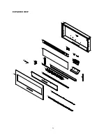
Page 20: ...20 EXPLODED VIEW...

Page 21: ...lugged into an electrical outlet Check plug and plug in Appliance has overheated and safety device has caused the thermal switch to disconnect Turn off the main switch allow appliance to cool for 10 m...

Page 22: ...22 SERVICE HISTORY This heater must be serviced annually depending on usage Date Dealer Name Service technician Name Service Performed Special Concerns NOTES...

Page 23: ...23...

Reviews: