background image

28 

Summary of Contents for 40-TRU-VIEW-XL

Page 1: ...explosion may result causing property damage personal injury or loss of life Do not store or use gasoline or other flammable vapors and liquids in the vicinity of this or any other appliance INSTALLER...

Page 2: ...G 26 SERVICE HISTORY 27 WARRANTY 28 INSTALLATION 11 MEDIA OPERATION 17 REMOTE CONTROL OPERATION 19 WIRING DIAGRAM 25 TABLE OF CONTENTS Please read and carefully follow all of the instruction found in...

Page 3: ...ners or the like Arrange the cord away from traffic area and where it will not be tripped over 7 Do not modify this fireplace Use it as described in the manual Any other use not recommended by the man...

Page 4: ...he one pictured below See Picture 1 2 Hold the male plug and insert it into the female receptacle The receptacle is locate on the left side if the fireplace 3 Please make sure the plugs are firmly con...

Page 5: ...This will save time and money later when you install the fireplace Before installation consider the following 1 Where the fireplace is located must allow for wall and ceiling clearances see INSTALLATI...

Page 6: ...Max NO HEATER 25W MOTOR HEATER 19W Appliance Width 43 1 4 or 109 7 cm Appliance Height 26 5 8 or 67 7 cm Appliance Depth 14 1 4 or 36 3 cm Gross Weight 121 3lbs or 55kg Plug Location Left side Cord Le...

Page 7: ...Max NO HEATER 25W MOTOR HEATER 19W Appliance Width 53 1 4 or 135 2 cm Appliance Height 26 5 8 or 67 7 cm Appliance Depth 14 1 4 or 36 3 cm Gross Weight 123 5lbs or 56kg Plug Location Left side Cord Le...

Page 8: ...Max NO HEATER 25W MOTOR HEATER 19W Appliance Width 63 1 4 or 160 6 cm Appliance Height 26 5 8 or 67 7 cm Appliance Depth 14 1 4 or 36 3 cm Gross Weight 141lbs or 64kg Plug Location Left side Cord Len...

Page 9: ...W Max NO HEATER 25W MOTOR HEATER 19W Appliance Width 75 1 4 or 191 cm Appliance Height 26 5 8 or 67 7 cm Appliance Depth 14 1 4 or 36 3 cm Gross Weight 165lbs or 75kg Plug Location Left side Cord Leng...

Page 10: ...SAFETY DRILL SCREW AREA There is a safety drill screw area as show below Please make sure that the fix screws are in this area Safety drill screw area Dark area 10 The manual control pad position...

Page 11: ...picture shows Note After removing framing plates on the left and right sides screw back the screws INSTALLATION The TRU VIEW XL models are designed to be built in and allow for the finishing material...

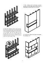
Page 12: ...ls with protective plastic bag and install plywood or drywall 6 Insert the fireplace into the wall opening Drive the mounting screws into the frame plates on the unit and the wall studs To fix the bot...

Page 13: ...w back the screws Installation for Front and Right Side Viewing 1 To install the fireplace where the left side is close to a wall and you want to view the fire from front and right side take off the f...

Page 14: ...ds To fix the bottom of the fireplace and the wall studs with the framing plates that you ve removed from left and right side of the fireplace at STEP 4 Plug in and check if the fireplace works 8 Deco...

Page 15: ...w back the screws Installation for Front and Left Side Viewing 1 Install the fireplace where the right side is close to a wall and you want to view the fire from front and left side take off the fendi...

Page 16: ...ce and the wall studs with the framing plates that you ve removed from left and right side of the fireplace at STEP 4 Plug in and check if the fireplace works 8 Decorate the plywood or drywall with gl...

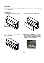
Page 17: ...media into the tray as shown below Feel free to use any combination of fire glass media that you find most appealing 5 Put back the front glass and screw back the bracket 3 Takeoffthefrontglasspanelan...

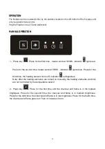
Page 18: ...lights blue Press for the third time the heating element turns off indicator extinguishes Note after the heating elements are turned on manually the heating elements work but are not controlled by th...

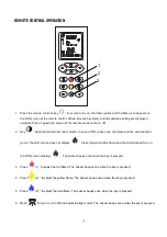
Page 19: ...screen of the remote control will turn off 2 Key flame and charcoal control switch In case of ON press once the flame and the charcoal bed go out the LCD screen does not display Press it again and the...

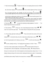
Page 20: ...etween 7 and 30 The buzzer beeps when the key is pressed 9 Press shift key Press once the corresponding figure flashes Press now to set current time and week The buzzer does not beep when the key is p...

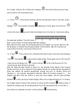
Page 21: ...splays icon the indicator on the machine lights yellow Press again to turn it off the LCD screen does not display icon and the indicator on the machine goes off The buzzer beeps when the key is presse...

Page 22: ...ttery items in separate collection schemes which cater for the recovery and recycling of materials contained within Your co operation is vital to ensure the success of these schemes and for the protec...

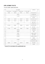
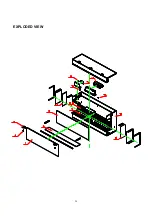
Page 23: ...0701284 10701219 10701220 10701221 BACK GLASS WITH BLACK PLASTIC 1 6 10701222 SIDE CLEAR GLASS 2 7 601136B 601136B 601136B 601137B LED STRIP FOR TRAY AND FLAME 8 3151505 3123505 3124505 3125505 FLICKE...

Page 24: ...EXPLODED VIEW 24...

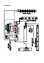
Page 25: ...25 Wiring Diagram...

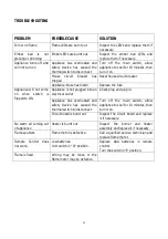
Page 26: ...plugged into an electrical outlet Check plug and plug in Appliance has overheated and safety device has caused the thermal switch to disconnect Turn off the main switch allow appliance to cool for 10...

Page 27: ...27 SERVICE HISTORY This heater must be serviced annually depending on usage Date Dealer Name Service technician Name Service Performed Special Concerns NOTES...

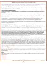
Page 28: ...28...

Reviews: