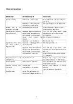
Amantii 2939-TRU-VIEW-XL Installation And Operation Instructions Manual Download Page 19

19 


TROUBLE SHOOTING 


PROBLEM 

POSSIBLE CAUSE 

SOLUTION 

Dim or no flame 

Flame LED’s are burnt out. 

Inspect the LED’s and replace them if 
necessary. 

Back black cloth is falling off 
and rolled up in the flicker. 

Change a flicker and back black cloth. 

Ember 

bed 

is 

not 

glowing or dimming 

Ember LED’s are burnt out 

Inspect the ember bed LED’s and 
replace them if necessary. 

Appliance turns off and 
will not turn on 

Appliance has overheated, and 
safety device has caused the 
thermal switch to disconnect. 

Turn  off  the  main  switch,  allow 
appliance to cool for 10 minutes,  
turn back on. 

House 
tripped. 

circuit 

breaker 

has  Reset house circuit breaker. 

Appliance’s fuse has blown. 

Replace the fuse. 

Appliance  will  not  come 
on 

when 

switch 

is 

flipped to ON 

Appliance is not plugged into an 
electrical outlet. 

Check plug and plug in. 

Appliance has overheated and 
safety device has caused the 
thermal switch to disconnect. 

Turn  off  the  main  switch,  allow 
appliance to cool for 10 minutes, turn 
back on. 

Circuit board is burnt out. 

Inspect the circuit board and replace 
it if necessary. 

No warm air coming out 
of appliance 

Heater is burnt out. 

Inspect  the  burner  and  heater 
assembly and replace it if necessary. 

Flame sputters 

Flame motor is defective. 

Call a qualified service technician and 
replace flame motor. 

Remote  Control  does 
not work. 

Low batteries. 
Unit switch in “O” position. 

Replace  AAA    batteries    in  remote 
control. 
Turn the switch in “I” position. 

Flame is fixed. 

Wiring may be loose or the 
flame motor may be defective. 


Summary of Contents for 2939-TRU-VIEW-XL

Page 1: ...ER RETAIN OWNER S MANUAL FOR FUTURE REFERENCE SAFETY INFORMATION WARNING For your safety always comply with all warnings and safety instructions contained in this manual to prevent personal injury or...

Page 2: ...AUTO MODE 13 REMOTE CONTROL OPERATION 14 INSTALLING WALL THERMOSTAT 15 REPLACEMENT PARTS 16 WIRING DIAGRAM 17 EXPLODED VIEW 18 TROUBLESHOOTING 19 SERVICE HISTORY 20 WARRANTY 21 Table of Contents Pleas...

Page 3: ...ion cord or relocatable power tap outlet power strip 12 Always use properly grounded fused and polarized outlets 13 Always use ground fault protection where it is required by electrical codes 14 Alway...

Page 4: ...r use on 120 volts The cord has a plug as shown in A An adapter as shown in C is available for connecting three blade grounding type plugs to two slot receptacles The green grounding lug extending fro...

Page 5: ...e with local codes In the absence of local codes use the current CSA C22 1 Canadian Electrical Code in Canada or the ANSI NFPA 70 National Electrical Code in the United States Description ELECTRIC FIR...

Page 6: ...22W 180 cm 76 27 x 100 87 cm This appliance has been tested in accordance with the UL Standard 2021 for fixed and location dedicated electric room appliances in the United States and Canada If you ne...

Page 7: ...r horizontally use a spirit level to achieve this Fig 1 Fig 2 3 Check the wall to ensure there is no wiring pipe wires etc in the area to be drilled Drill 8 or more pilot holes 8m m diameter 40mm dept...

Page 8: ...the appliance from the box Prior to installation test to make sure the fireplace operates properly 2 Get the bracket and framing from the parts kit and screw them to the fireplace as shows below brack...

Page 9: ...se the brackets you used in Step 2 to fix the completed mantel to the fireplace 4 After checking that the fireplace operates properly you may now decorate the surrounding area with a finish of your ch...

Page 10: ...es are suitable for installation in outdoor areas protected from direct water impingement In addition to maintaining the listed mantel and combustibles clearances a rain protection overhang factor of...

Page 11: ...alified this electric appliance If it is necessary to hard wire this appliance consult a qualified electrician wired do so in accordance with local codes In the absence of local codes use the current...

Page 12: ...denly STEP 3 Remove the front glass panel to decorate your fireplace Pour the decorative media into the tray Feel free to use any combination of fire glass media that you find most appealing STEP 4 Af...

Page 13: ...current heater settings OUTPUT OUTPUT Under this mode the heater will automatically turn ON at high heat setting 1500W heat output wh the room temperature drops below 22 72 When the room temperature...

Page 14: ...iver to respond to the transmitter Do not PRESS the buttons more than once within two on button at top left corner of the remote is the main ON OFF all the functions and the fireplace will be in stand...

Page 15: ...24 VAC Install Wall Thermostat per instructions provided with kit and per the following information 1 Turn off circuit breaker 2 Remove cover plate located on the left side of appliance 3 Pull the wi...

Page 16: ...PANEL 2 5 10702242 VISUAL GLASS 1 6 10702243 BOTTOM GLASS 1 7 602082 BLOWER AND HEATER ASSEMBLY 1 8 601036 CONTROL PANEL 1 9 10104002 SWITCH 1 11 601097B CIRCUIT BOARD 1 12 301506 REMOTE RECEIVER 1 1...

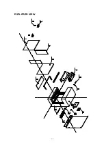
Page 17: ...EXPLODED VIEW 17...

Page 18: ...Wiring Diagram 18...

Page 19: ...fuse has blown Replace the fuse Appliance will not come on when switch is flipped to ON Appliance is not plugged into an electrical outlet Check plug and plug in Appliance has overheated and safety de...

Page 20: ...20 SERVICE HISTORY This heater must be serviced annually depending on usage Date Dealer Name Service technician Name Service Performed Special Concerns NOTES...

Page 21: ...of purchase of the cover is required for any warranty claims Defects Defects must be brought to the attention of the selling dealer Please have your proof of purchase catalogue model and serial number...

Reviews: