15
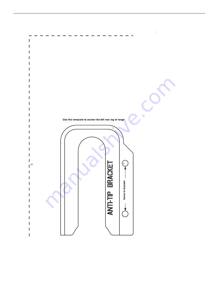
ANTI-TIP BRACKET TEMPLATE
Cut on dotted lines and place the left edge against the left side cabinet and the top edge against the rear wall.
Left edg
e
Top edge
Page 1: ...ements 3 Electrical Requirements U S A Only 4 INSTALLATION INSTRUCTIONS 6 Unpack Range 6 Install Anti Tip Bracket 6 Electrical Connection U S A Only 7 Verify Anti Tip Bracket Location 12 Level Range 1...
Page 2: ...n this manual and on your appliance Always read and obey all safety messages This is the safety alert symbol This symbol alerts you to potential hazards that can kill or hurt you and others All safety...
Page 3: ...m of 5 12 7 cm beyond the bottom of the cabinets Cabinet opening dimensions that are shown must be used Given dimensions are minimum clearances The floor anti tip bracket must be installed To install...
Page 4: ...odes Do not use an extension cord Be sure that the electrical connection and wire size are adequate and in conformance with the National Electrical Code ANSI NFPA 70 latest edition and all local codes...
Page 5: ...ck of the range or inside the storage drawer in a clear plastic bag If connecting to a 4 wire system This range is manufactured with the ground connected to the neutral by a link The ground must be re...
Page 6: ...pping base cardboard or hardboard 1 Remove template from the anti tip bracket kit found inside the oven cavity or from the back of this manual 2 Place template on the floor in cabinet opening so that...
Page 7: ...ware store ElectricalConnection U S A Only Power Supply Cord Direct Wire 1 Disconnect power 2 Remove the terminal block cover screws located on the back of the range Pull cover down and toward you to...
Page 8: ...area where local codes prohibit grounding through the neutral 1 Part of metal ground strap must be cut out and removed 2 Use a Phillips screwdriver to remove the ground link screw from the back of th...
Page 9: ...chassis ground conductor to neutral wire of power supply cord 1 Feed the power supply cord through the strain relief on the cord conduit plate on bottom of range Allow enough slack to easily attach t...
Page 10: ...ires through the strain relief on bottom of range Allow enough slack to easily attach wiring to the terminal block 4 Attach terminal lugs to line 1 black neutral white and line 2 red wires Loosen do n...
Page 11: ...n the following Bare Wire Torque Specifications chart Bare Wire Torque Specifications Attaching terminal lugs to the terminal block 20 lbs in 2 3 N m 3 Use nut driver to connect the bare green ground...
Page 12: ...ped with Warming Drawers Use a wrench or pliers to adjust leveling legs up or down until the range is level Push range back into position Check that rear leveling leg is engaged in anti tip bracket NO...
Page 13: ...your tools 3 Dispose of recycle all packaging materials 4 Check that the range is level See Level Range 5 Use a mild solution of liquid household cleaner and warm water to remove waxy residue caused b...
Page 14: ...wired ranges 1 Disconnect power 2 Slide range forward 3 Complete cleaning or maintenance 4 Check that anti tip bracket is installed Look for the anti tip bracket securely attached to floor Slide range...
Page 15: ...15 ANTI TIP BRACKET TEMPLATE Cut on dotted lines and place the left edge against the left side cabinet and the top edge against the rear wall Left edge Top edge...
Page 16: ...W10252706B 2009 All rights reserved 9 09 Printed in U S A...