background image

6

ELECTRICAL CONNECTIONS

HIGH VOLTAGE!


D

ISCONNECT

 ALL 

POWER


BEFORE


SERVICING

. M

ULTIPLE


POWER


SOURCES


MAY


BE


PRESENT

. F

AILURE


TO


DO


SO


MAY


CAUSE


PROPERTY


DAMAGE

PERSONAL


INJURY


OR


DEATH


DUE


TO


ELECTRIC


SHOCK

. W

IRING


MUST


CONFORM


WITH

 NEC 

OR


CEC 

AND


ALL


LOCAL


CODES

. U

NDERSIZED


WIRES


COULD


CAUSE

POOR


EQUIPMENT


PERFORMANCE

EQUIPMENT


DAMAGE


OR


FIRE

.

Determine the availability of sufficient power to operate the unit.
The voltage at the power supply must correspond to the unit RATED
VOLTAGE REQUIREMENT.

Determine wire sizes from the unit nameplate ampacity and in
accordance with the National Electrical Code. Wiring should never
be sized smaller than is recommended by either of these two
sources.

The unit must be permanently grounded in accordance with local
codes, or in the absence of local codes, with the N.E.C. ANSI/NFPA
NO. 70-1987 or latest edition in the U.S.A.

Internal Wiring

A diagram of the internal wiring of this unit is located under the
electrical box cover. If any of the original wire as supplied with
the appliance must be replaced, the wire gauge and insulation
must be same as original wiring.
Transformer is factory wired for 230 volts on 208/ 230 volt mod-
els. See wiring diagram for 208 volt wiring. For 208V operation,
move the red wire lead from 240V to 208V tap.

THERMOSTAT HEAT

ANTICIPATOR SETTING

ALL MODELS

0.2

MODEL

Table 4

Make the following high and low voltage connections at either
location to wire units.

High Voltage Wiring

This unit is designed for Single phase 208/230 Volt only. Connect
the two leads to terminals L1 and L2 on the disconnect in the
electrical control section, using wire sizes specified in Table 1.

Low Voltage Wiring

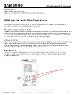
For ACNF18, ACNF24 and ACNF30 models, refer to Figure 6 for
cooling unit with electric heat and refer to Figure 7 for heat pump
with electric heat.

NOTE

:  HPSK-01 Heat Pump Shut-Off Relay Kit (C.R.I.) must be used

when ACNF with electric heat installed with heat pump.

THERMOSTAT

BLUE

YELLOW

TO CONDENSING UNIT

24 V CONNECTIONS

W

R Y G

Figure 6

2

4

5

6

1

3

C.R.I.

* W

R

B

I

W

Br

G

R

W

2

O

Y

C

CEILING MOUNT UNIT

* W

* Y

* B

I

R

O

Y

E

G W

2

C

THERMOSTAT

HEAT PUMP

*WIRES SUPPLIES WITH HPSK KIT

Note: in case of heat pump failure, switch to "E" on Thermostat for

emergency heat.  See note under Low Voltage Wiring

Figure 7

Connect low voltage wires from the thermostat to the corre-
sponding wires in the Ceiling Mount unit and outdoor unit  using
No. 18 AWG wires as follows:

LEAD

THERMOSTAT

NOTES

RED

R (24V)

-

GREEN

G (FAN)

-

-

Y

TO CONDENSING UNIT 

24V CONNECTIONS

WHITE

W

-

BLUE

-

TO CONDENSING UNIT 

24V CONNECTIONS

BROWN

E

TO BE USED FOR 

EMERGENCY HEAT ONLY

Table 5

Summary of Contents for ACNF180 Series

Page 1: ... DAMAGE ARISING FROM IMPROPER SERVICE OR SERVICE PROCEDURES IF YOU SERVICE THIS UNIT YOU ASSUME RESPONSIBILITY FOR ANY INJURY OR PROPERTY DAMAGE WHICH MAY RESULT IN ADDITION IN JURISDICTIONS THAT REQUIRE ONE OR MORE LICENSES TO SERVICE THE EQUIPMENT SPECIFIED IN THIS MANUAL ONLY LICENSED PERSONNEL SHOULD SERVICE THE EQUIPMENT IMPROPER INSTALLATION ADJUSTMENT SERVICING OR REPAIR OF THE EQUIPMENT SP...

Page 2: ...lable in cooling capacities of 1 5 2 and 2 5 nominal tons of cooling with a PSC motor ACNF18 ACNF24 and ACNF30 and 2 and 2 5 nominal tons of cooing with a constant torque EEM motor ACNF25 and ACNF31 Electric heat models are available in capacities of 0 5 6 8 and 10 kW The unit is designed to be installed in a horizontal position above a dropped ceiling Do NOT install this unit outside the structur...

Page 3: ...e A drain trap in a draw through application prevents air from being drawn back through the drain line during fan operation thus preventing condensate from draining and if connected to a sewer line to prevent sewer gases from being drawn into the air stream during blower operation In a blow through application the drain trap prevents conditioned air from escaping It is per missible in this applica...

Page 4: ... 1 Before locating the unit on the dropped ceiling ensure the strength of the ceiling and beams is adequate to support the weight involved This is an important step and the installers responsibility See the table below for approximate weight of unit MODEL WEIGHT lb 1 5 TON 57 2 TON 64 2 5 TON 68 Table 2 2 Mount the unit in a horizontal position above a dropped ceiling of adequate strength Refer to...

Page 5: ...ing the serial plate or the finish on the unit Heat trap or wet rags should be used to protect heat sensitive components such as service valves and TXV valves TO PREVENT FEEDER TUBE DAMAGE HOLD THE DISTRIBUTOR BODY WITH A 3 4 OPEN END WRENCH WHEN REMOVING OR REPLACING THE 13 16 FLARE NUT CAUTION 1 Remove the valve core to allow high pressure tracer gas to escape No gas indicates a possible leak 2 ...

Page 6: ...08 volt wiring For 208V operation move the red wire lead from 240V to 208V tap THERMOSTAT HEAT ANTICIPATOR SETTING ALL MODELS 0 2 MODEL Table 4 Make the following high and low voltage connections at either location to wire units High Voltage Wiring This unit is designed for Single phase 208 230 Volt only Connect the two leads to terminals L1 and L2 on the disconnect in the electrical control secti...

Page 7: ...ters every month This routine maintenance procedure will pay big dividends in reduced operating cost and reduced service ex pense Never operate comfort equipment without filter s Fuses and or Circuit breakers This comfort equipment should be connected to the building elec tric service in accordance with local and National Electric codes This electrical connection will include over current protecti...

Page 8: ...fg com or www amana hac com for information on Products Warranties Customer Services Parts Contractor Program and Training Financing Options is a registered trademark of Maytag Corporation or its related companies and is used under license All rights reserved BLOWER CHART FOR ACNF 0 1 0 2 0 3 0 4 0 5 High 710 660 590 515 435 Low 650 595 540 480 390 High 955 880 820 740 675 Low 885 840 775 725 620 ...

Reviews: