AM Solar Deluxe Upgrade 99-TRLSIG Installation Manual Download Page 16

Updating Your Victron Color Control Display (Page 1/2)

Programming Your Victron Color Monitor

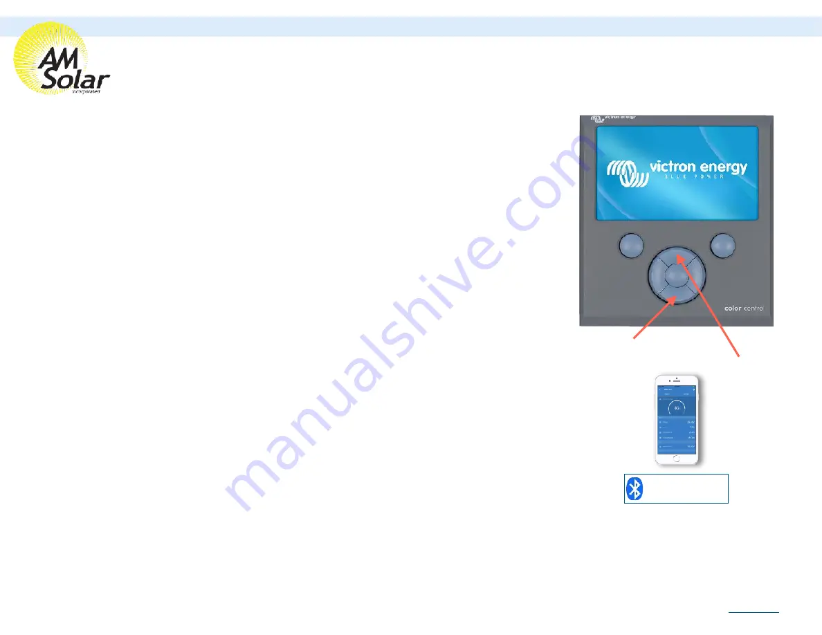
These devices connect via 

Bluetooth to communicate 
with a smartphone using the 

VictronConnect app. 

Connecting Your Victron Display to Wireless: 

1. Press the top right button on the display (menu), and use the down directional button to scroll to Settings. 

Enter the Settings screen by pressing the center button when “Settings” is highlighted.

2. Use the down directional button to scroll to “Wifi” (near the bottom of the list). Press the center button when 

highlighted to enter Wifi.

3. Highlight the network you are connecting with, using the up and down directional buttons to scroll if needed. 

Press the center button to connect once the wireless network is highlighted.


If a password is required, it will prompt you here. Use the up and down directional buttons to select 

letters. Press the right directional button to move to the next letter. Press the center button when the full password 
is entered.

4. The connection could take up to 1 minute to complete. Ensure it displays “connected” when done. You now 

have internet access to your display. Be sure to remain within the wireless signal range during the duration of 
the firmware upgrade in the next step.

Updating The Display Firmware: 

1. Use the left direction button to go back to the “Settings” screen. 

2. Use the down directional button to scroll to “Firmware” (2nd down from the top), and press the center button 

once highlighted.

3. Select “Online updates”.  Press the center. Button once highlighted.

4. Select “Check for Updates”. It will proceed with checking for updates.

5. Select “Perform Updates”. It can take up to 5 minutes for the updates to be applied and the system to reboot.

6. It should now display a message stating it’s on the latest version in the “Firmware” section.

Helpful Notes: 

Pressing the center button will always select what is highlighted.

Pressing the left arrow will take you back to the previous screen.

Pressing the top right button will pull up the Settings page.

Bottom Directional Button

Top Directional Button

AM Solar Inc.

3555 Marcola Rd.

Springfield, OR 97477

541.726.1091

www.amsolar.com

Rev.20190813

Summary of Contents for Deluxe Upgrade 99-TRLSIG

Page 1: ...99 TRLSIG Deluxe Upgrade Installation Guide AM Solar Inc 3555 Marcola Rd Springfield OR 97477 541 726 1091 www amsolar com Website Link Rev 20190813...

Page 2: ...ch subsystem in the kit Complete bill of materials broken down by subsystem listing quantities part numbers and descriptions with QR codes to link data sheets for major components Detail of the Batter...

Page 3: ...ll wire runs rope for heavy gauge and label them tape and stickers works well Then layout the all the components that fit the interior of your rig to prepare for installation Keep it organized Stay or...

Page 4: ...eat time to schedule your installation work with the professionals at AM Solar Sturdy Ladder Hammer Crimper Hammer Heat Gun Wire Crimper Wire stripper Cable Cutter Multimeter Screwdriver Smartphone Dr...

Page 5: ...26 1091 www amsolar com To 2nd Solar Panel 99 TRLSIG Deluxe Upgrade System Overview Main AC Panel SPS Transfer Switch Back of Solar Panel s with Rocker Foot Mounts Fuse Modified Zamp 100W Solar Panel...

Page 6: ...xe Upgrade Bill of Materials AM Solar Inc 3555 Marcola Rd Springfield OR 97477 541 726 1091 www amsolar com Solar Panels Charge Controller Inverter 3000 Lithium Batteries Color Control Lithium Base Ki...

Page 7: ...Used Cut and Cap Wire To Engine Battery DC Loads Red Post 93P RED TEMP BS FUSE MEGA 250A CABLE VT M8 1 CABLE 2GA 1 RED CABLE 18GA 1 YLW CABLE 4 0 1 BLK CABLE 4 0 1 BLK CABLE 18GA 2 GRY LUG 4 0 RING 3...

Page 8: ...99 TRLSIG Deluxe Upgrade Lithium Control Board AM Solar Inc 3555 Marcola Rd Springfield OR 97477 541 726 1091 www amsolar com AM Solar Lithium Control Board Rev 20190813...

Page 9: ...nc 3555 Marcola Rd Springfield OR 97477 541 726 1091 www amsolar com 50 TSFMB1 LUG 4 0 RING 3 8 Main AC Panel SPS BOX PD5500 LUG 4 0 RING 3 8 93H B3 4 93H R3 4 RJ45 PORT1 MAINS DETECTOR BLUE NOTE The...

Page 10: ...N L2 Inverter Output Inverter Input L 1 N L2 SHORE IN Do Not Connect Shore Here L 1 N L2 99 TRLSIG Deluxe Upgrade SPS Wiring AM Solar s SPS Full Passthrough All the time Fuse Connect loose black 18g...

Page 11: ...Panel Mounted Dimensions 39 56 x 19 88 x 1 38 MOUNTA 35 MOUNTA 35 MOUNTA 35 MOUNTA 35 MOUNTL 3 MOUNTL 3 MOUNTL T3 MOUNTL T3 FSTBLT TKNOB FSTBLT TKNOB FSTBLT TKNOB FSTBLT TKNOB FSWASH FLT 5 16 FSWASH...

Page 12: ...7 Mode Leave on B 8 Alarm output Select Relay from the menu 2 Select BatteryProtect from VictronConnect 5 Select User defined from the Preset menu 7 Mode should be set to Relay mode 8 Alarm output Sel...

Page 13: ...iciency Factor 98 12 Go back to settings enter Misc 13 Temperature Unit Fahrenheit 14 Aux Input User Option Temp 15 Exit from the device NOTE Only one phone can be connected to each device at a time B...

Page 14: ...een Click on the 3 buttons to the right of the controller image and select Reset PIN Code 5 Click on the gear in the top right corner 6 Click on Battery 7 Click on the settings and adjust them accordi...

Page 15: ...etwork picture 3 5 Enter a name for your network picture 4 Linking Each Device 1 Enter the Victron Connect App and click on a device 2 Go to Settings shown as a gear symbol in the top right picture 1...

Page 16: ...is entered 4 The connection could take up to 1 minute to complete Ensure it displays connected when done You now have internet access to your display Be sure to remain within the wireless signal range...

Page 17: ...d set date time 6 Go back to settings enter General then select reboot 7 Enter settings once rebooted then enter Services and turn on VRM two way communication 8 Go to Settings then enter System Setup...

Reviews: