Alula RE114 Quick Start Manual Download Page 1

IN

STA

L

L

G

U I D E

I

Smoke Alarm 

is a fire-protection device 

that alarms when it detects smoke or 

temperatures above 135°F (57°C).

Features

•  UL217 and ULC531 listings

•  Smoke and heat detection

•  5 year warranty

Quick Start Guide 

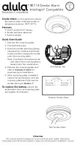
1.  Remove the mounting plate.
2.  Pull the battery tab.
3.  Enroll the smoke alarm by placing 

the panel into wireless enrollment 

mode and then twisting the smoke 

onto the mounting plate.
Note: Enrollment transmissions are 

sent when the mounting plate is 

twisted onto the smoke alarm.

4.  Remove the mounting plate and 

refer to 

Sections 2 and 6

 for 

positioning and installation.

5.  After mounting plate is installed 

restore the smoke alarm onto the 

mounting plate and fully test the 

smoke alarm per 

Section 7

To replace the battery, 

detach the 

smoke alarm from its mounting plate 

and replace the batteries. 


Attention


This manual should be read prior to use and retained for further information.

Verify proper enrollment and operation using your security panel’s installation manual.

Test Smoke Alarm

Pull Battery Tab

Position Smoke Alarm

12 inches

minimum

12 inches

minimum

Resolution Compatibles

RE114 Smoke Alarm 

Interlogix

®

 Compatible

Summary of Contents for RE114

Page 1: ...isted onto the smoke alarm 4 Remove the mounting plate and refer to Sections 2 and 6 for positioning and installation 5 After mounting plate is installed restore the smoke alarm onto the mounting plat...

Page 2: ...s every 48 sec 2 Beeps End of Life Off 3 Flashes every 48 sec 3 Beeps Silence Sounding Alarm Press Release Button 1 Flash every 8 sec Off Off for 10 mins Silence End of Life indication up to 30 days P...

Page 3: ...every level of a dwelling unit including basements 4 On every level of a residential board and care occupancy small facility including basements and excluding crawl spaces and unfinished attics 5 In t...

Page 4: ...Smoke Alarms must be mounted away from corners Keep at least 305mm 12 from walls and corners see Figure 3 Additionally mount the unit at least 305mm 12 from any light fitting or decorative object whic...

Page 5: ...ry replacement Locate the Alarm at least 1m 39 from dimmer controlled lights and wiring as some dimmers can cause interference Locate Alarm at least 1 5m 59 and route wiring at least 1m away from fluo...

Page 6: ...press the test hush button Do not attempt to recharge or burn the battery as it may explode If it is necessary to remove the battery for separate disposal handle carefully to avoid possible eye damag...

Page 7: ...the alarm sound or to those who may be incapable of safely evacuating the area unassisted Limitations of Heat Alarms There are various situations where a Heat Alarm may not be effective Fires where th...

Page 8: ...essary it is possible to further secure the Alarm by using a No 2 or No 4 2 to 3mm 1 8 diameter not supplied self tapping screw 6 to 8mm 1 4 long see Figure 7d to firmly lock the Alarm and its mountin...

Page 9: ...ith a damp cloth and dry thoroughly WARNING Do not paint your Alarm Other than the maintenance and stop sounding shortly after the button is released Repeat this procedure for all other Alarms in the...

Page 10: ...e chamber base 8 Fit a new chamber top and clip in place by turning clock wise 15 degrees 9 Insert the thermistor PCB into the sockets and ensure the thermistor is perpendicular to the chamber see fig...

Page 11: ...s check the replace by date marked on the side of the unit Before the Alarm is safely discarded remove from the mounting plate disconnect the batteries Do not put the Alarm into a fire The Alarm shoul...

Page 12: ...any interference including interference that may cause undesired operation of the device Le pr sent appareil est conforme aux cnr d Industrie Canada applicables aux appareils radio exempts de licence...

Reviews: