


VertilLine24 Series Installation Guide
- 7 -
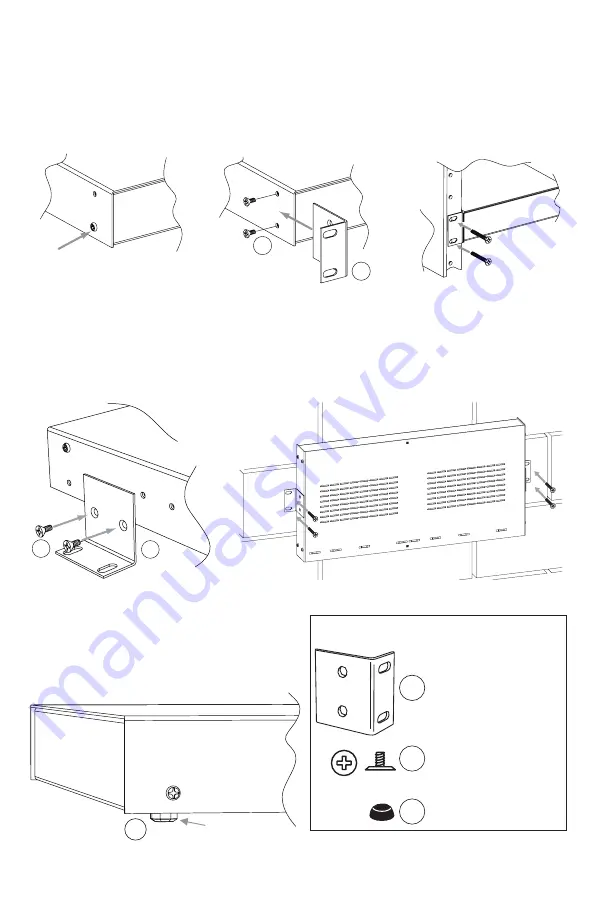
Fig. 4
Mounting Options:
Rack Mount Installation
1. Remove factory installed screws from both sides of the rack chassis
(Fig. 4a)
.
2. Install mounting brackets (A) on the left and right side of rack chassis
using the
two (2) flat head screws (B) (included)
(Fig. 4b)
.
3. Place unit into desired EIA 19” rack position and secure with mounting screws
(not included) (Fig. 4c).
B
A
Fig. 4a
Fig. 4b
Fig. 4c
Top
Top
Top
Front
Left
Front
Left
Front Left
Remove
––––––––––––––––––––––––––––––––––––––––––––––––––––––––––––––––––––––––––––––––
Wall Mount Installation
1. Install mounting brackets (A) on the left and right side of rack chassis
using
two (2) flat head screws (B) (included)
(Fig. 5a)
.
2. Place unit at desired location and secure with mounting screws
(not included) (Fig. 5b).
Caution:
It is necessary to make sure mounting screws are securely fastened to a beam when installing.
Fig. 5
Fig. 5a
Fig. 5b
B
A
Fig. 6
––––––––––––––––––––––––––––––––––––––––––––––––––––––––––––––––––––––––––––––––
Shelf Installation
1. Position and affix rubber pads (C) (included) at
each corner on the bottom of the unit
(Fig. 6)
.
2. Place unit in desired location.
A
B
C
Mounting Hardware
(Included):
C
Left Side
Rubber Pad
Two (2) mounting brackets
Six (6) flat head screws
for mounting brackets.
Four (4) rubber pads.