background image


Trove SALTO ULXB Kits Installation Guide 

- 5 - 

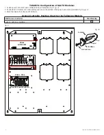
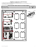
T2SAK7512: Configuration of SALTO Modules:

1.  Fasten spacers onto metal pems configuration (A) of backplane 

(Fig. 4, pg. 5)

.

2.  Position SALTO modules over corresponding spacers and mount them utilizing pan head screws (provided) 

(Fig. 4a, pg. 5)

.

3.  Mount backplane to enclosure with hardware.

Access Controller Position Chart for the Following Models:

SALTO Access Controller

Pem Mounting

CU42E0, CU4200 or CU4EB8

A

Fig. 4

TRG

TRIGGER

INPUT

ACM4

ACCESS POWER

CONTROLLER

LED1 

LED2 

LED3 

LED4

MAIN

OUTPUT 

1

NC   C   NO  COM

NC   C   NO  COM

NC   C   NO  COM

NC   C   NO  COM

OUTPUT 

2

OUTPUT 

3

IN  GND

1

IN  GND

2

IN  GND

3

IN  GND

4

OUTPUT 

4

--        +

CONTROL

--        +

POWER

+INP-      T      +RET-

INTERFACE

NO     C      NC

FACP

OUT1 

OUT2 

OUT3 

OUT4 

OUT5 

OUT6 

OUT7 

OUT8

Common 

Po

wer Outputs (NEG)

P

N

+ INP1 -   + INP2 -


DM1+

DM2+

Common(-)

DM2+

Common(-)

P

N

Fuse1

Fuse2 

Fuse3 

Fuse4 

Fuse5 

Fuse6 

Fuse7 

Fuse8

IN1 Fus

e

IN2 Fuse

DM1

+

Dual 

Voltage

Po

wer Distribution

Module

PDS8

8

Altronix

AL1012ULXB

OUTPUT 1     OUTPUT 2         OUTPUT 3         OUTPUT 4          OUTPUT 5        OUTPUT 6         OUTPUT 7        OUTPUT 8

NC  C  NO COM NC C NO COM  NC  C  NO COM NC C NO COM  NC  C  NO COM NC C NO COM  NC  C NO COM NC C NO COM

 IN  GND IN GND IN GND IN GND

IN  GND IN GND IN  GND IN GND

1            2           3          4

5           6           7           8

 INPUT

TRIGGER

10A 250V

+INP-  T + RET-

NO  C   NC

FACP            INTERFACE

Power   Control

-      +      -      

+

F1                   F2                  F3                   F4                   F5                   F6                   F7                   F8

MAIN

TRG

FACP

1     2     3     4

1     2     3     4

O N

O N

1     2     3     4

1     2     3     4

O N

O N

Altronix

ACM8

Altronix

ACM4

Altronix - PDS8

A

A

A

A

A

A

L

G

N

BAT FAIL

AC FAIL

NC

C

NO

NC

C

NO

AC

DC

-   BAT   

+

+   DC   - 

AC DELAY

Altronix

AL1024ULXB2

+ BAT 

-

L     G      N

BAT FAIL  NC  C  NO  NC   C   NO  AC FAIL

AC

DC

- DC 

+

Pem

Spacer

HS4 Module

Backplane

Pan Head Screw

Fig. 4a

Summary of Contents for Trove T1SAK34

Page 1: ...ve2 enclosure with TSA2 Altronix SALTO backplane 1 AL1024ULXB2 Power Supply Charger 1 AL1012ULXB Power Supply Charger 1 ACM8 Fused Access Power Controller 1 ACM4 Fused Access Power Controller 1 PDS8 D...

Page 2: ...ANSI and with all local codes and authorities having jurisdiction Product is intended for indoor use only 1 Remove backplane s from enclosure Do not discard hardware 2 Mark and predrill holes in the...

Page 3: ...IN2 Fuse PWR1 Altronix PDS8 1 2 3 4 5 6 7 8 Altronix VR6 is mounted under PDS8 A A BAT FAIL NC C NO NC C NO AC FAIL AC DC BAT BAT DC L G N OFF 24V ON 12V ON Altronix AL600ULXB T1SAK34 Configuration o...

Page 4: ...M PWR2 COM P N Fuse1 Fuse2 Fuse3 Fuse4 Fuse5 Fuse6 Fuse7 Fuse8 IN1 Fuse IN2 Fuse PWR1 1 2 3 4 5 6 7 8 OUTPUT 1 OUTPUT 2 OUTPUT 3 OUTPUT 4 OUTPUT 5 OUTPUT 6 OUTPUT 7 OUTPUT 8 NC C NO COM NC C NO COM NC...

Page 5: ...T2 OUT3 OUT4 OUT5 OUT6 OUT7 OUT8 Common Power Outputs NEG P N INP1 INP2 DM1 DM2 Common DM2 Common P N Fuse1 Fuse2 Fuse3 Fuse4 Fuse5 Fuse6 Fuse7 Fuse8 IN1 Fuse IN2 Fuse DM1 Dual Voltage Power Distribut...

Page 6: ...6 Trove SALTO ULXB Kits Installation Guide Notes...

Page 7: ...1 8mm 1 25 31 8mm 1 5 38 1mm 8 5 215 9mm 6 5 165 1mm 1 5 38 1mm 8 5 215 9mm 6 5 165 1mm 4 5 114 3mm 13 0 330 2mm 0 6 15 2mm 14 5 321 3mm 1 45 36 8mm 7 25 184 2mm 1 95 49 5mm 1 1 27 9mm 0 6 15 2mm 0 57...

Page 8: ...35mm 5 25 133 35mm 6 25 158 8mm 1 25 31 8mm 0 85 21 6mm 0 5625 14 3mm 2 415 61 3mm 0 685 17 4mm 1 77 45mm 0 885 22 5mm 1 125 28 3mm Knockouts 2 00 50 8mm 2 00 50 8mm T2SAK78 and T2SAK7512 Enclosure D...

Reviews: