background image

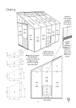
25 


610  

x  

1635 

610  

x  

1635 

610 x 642


610  

x  

868 

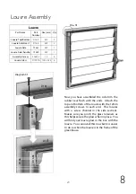
Plain Gable 

Use the 

glass 

separators 

between 2 

panes of 

glass and 

above and 

below the 

louvre   

Keep the 

short flange 

pointing 

upwards on 
the outside. 

The louvre can 

replace any of the 

610x1635 panes 

610  

x  

1635 

100 

x  

525 

610

 x 1

53 

610  

x  

1635 

610  

x  

868 

610  

x  

1635 

61

0 x

 15

20


610

 x 1

520


610

 x 1

520


610 x

 642 

610 x 6

10 

610 x

 642 

610  

x  

1635 

558 

x  

997 

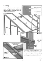
Glazing


Note:  

All channels in 

the aluminium 

capping should have 

rubber inserted, 

even if it is going 

onto the timber.  

61

0 x

 15

20


610 x 6

10 

610

 x 1

520


610  

x  

1635 

610  

x  

1635 

610 x 153 

100 

x  

525 

Summary of Contents for Evolution Six LT

Page 1: ...07 15...

Page 2: ...ly Plain Gable Assembly Frame Assembly Louvre Assembly Glazing Door Installation Ridge Cover Cap Installation Roof Vent Installation Frame Finishing Gutter and Downpipe Installation Parts Lists Option...

Page 3: ...e will provide the most solid foundation for your greenhouse A slabbed base would be our preferred choice as this helps with drainage Avoid placing your greenhouse under trees or in other vulnerable l...

Page 4: ...enhouse is relatively easy to get to and convenient to bring water to and possibly a supply of electricity Finally and most importantly choose a site where your Alton Greenhouse will look right so tha...

Page 5: ...t out your metal base on your prepared site but don t fix this down until the greenhouse is complete Follow the manual and build the sections as recommended When screwing through one piece of timber i...

Page 6: ...site a waterbutt when doing this Extension and Partition instructions are in separate booklets Be sure to follow these instructions at the correct time in the build For an extension this will be durin...

Page 7: ...ngth of building you have in the table below to check which parts you should be using Use the crop head bolts along the bolt channels for attaching the base brackets D174M diagram 2 The base brackets...

Page 8: ...osition fix with the 50mm screw Now slot the eaves rail into position e g EV0021 There is no need to fix this yet as it is done at a later stage Front Assembly 4 Part Number Size mm Qty EV0015 1846 2...

Page 9: ...he way in you may find they need a light tap with a wooden mallet or something similar If you are going to glue your joints this is the first point you would do this 50mm Screw Pilot hole it is easies...

Page 10: ...10 Left Hand Door Gable Assembly 5 Right Hand Door Gable Assembly EV0068 EV0093 EV0108 EV0006 EV0006 EV0094 EV0096 EV0095 EV0069 EV0108 EV0006 EV0006 EV0044 EV0045 Dia 6 Dia 7 Dia 8 Dia 9 Dia 11...

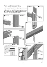
Page 11: ...the drill bit supplied diagram 6 7 and 8 First slot the door header EV0108 onto the gable bars and fix with 50mm screws Then do the same with the cills Next drill through the gable bars at the lap jo...

Page 12: ...12 Left Hand Plain Gable Assembly 6 Right Hand Plain Gable Assembly EV0068 EV0093 EV0107 EV0010 EV0094 EV0096 EV0095 EV0069 EV0107 EV0010 EV0044 EV0045 Dia 13 Dia 14 Dia 15 Dia 16 Dia 18...

Page 13: ...rts out flat on the floor again as you did with the door gable Drill and fix the parts in the same way as before but this time use the door header insert EV0107 in the top mortise holes of the gable b...

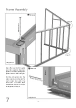
Page 14: ...at different heights to each other so the screws don t intersect each other Now offer the side corner bar EV0057 to the eaves bar slotting the tenon into the mortise shown in diagram 20 do not fix th...

Page 15: ...15 Dia 20 Dia 21 Frame Assembly 7 Diagram 21 80mm Screw Keep faces in line EV0057 16mm 16mm Front Base Plain Gable Base 15mm 25mm Side Cill External Diagram 20 EV0057 Eaves Bar External Outside Edge...

Page 16: ...22 42m m External Dia 23 Dia 22 Now offer up the first gable end this could be the plain gable or the door gable plain gable shown in this example Slot the cill section into the side corner bar and lo...

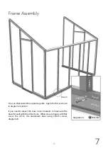
Page 17: ...4 You can then install the opposite gable Again fix this as shown in diagram 22 and 23 If you need to adjust the base corner brackets to make sure the base fits well with the cill sections When you ar...

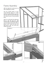
Page 18: ...m Screw Dia 25 Diagram 25 Diagram 26 With help slot the ridge into the two gable ends diagram 25 Drill a pilot hole in the roof corner bar at an angle similar to the 50mm screw shown in diagram 26 fi...

Page 19: ...s First you should install an eaves spacer EV0024 diagram 27 Make sure this is pushed all the way up to the roof corner bar and fix this with two 50mm screws in the pre drilled holes Now slot a roof b...

Page 20: ...nce all the roof bars are in place slide the building away from the wall enough to stick the foam strip to the ridge and wall bars diagram 30 This comes in 7 meter rolls If you have a slightly uneven...

Page 21: ...for the front of the building to get the eaves level It is important that the ridge and eaves are parallel as any twist in the building will make glazing difficult When you are happy with the positio...

Page 22: ...ly 8 To start building your louvre you first need to assemble the sides Connect the two side section with the two inserts as shown here D166 D166 D168L D168L Pinch all glass retainers before glazing D...

Page 23: ...m the rubber seal flush with the ends Attach the top and bottom of the louvre with the 12mm assembly screws In each end This locates with a screw channel in the side sections Makes sure you pinch the...

Page 24: ...or the upgrade aluminium capping If you have the Aluminium capping you need to slide the glazing rubber into channels on the back of the capping Use a Stanley knife or scissors to cut to length it is...

Page 25: ...The louvre can replace any of the 610x1635 panes D A B A D 610 x 1635 100 x 525 610 x 153 610 x 1635 610 x 868 610 x 1635 C D 610 x 1520 610 x 1520 610 x 1520 610 x 642 610 x 610 610 x 642 610 x 1635...

Page 26: ...at there is no interference with the glass in the location that you choose Make sure you fit it the right way up the handle is always on the right standing on the inside Once in position fix the next...

Page 27: ...place while you get the next section of glass in place Always keep the glazing capping flush to the aluminium base level with the bottom of the glass Once the vertical capping is on you can fit the r...

Page 28: ...35 Next you need to decide on the location of your roof vents These can NOT be fitted side by side Once you have decided this start by installing the glass that goes underneath the vent Use 2 of the g...

Page 29: ...10 X 1520 External Diagram 37 Glass stop over screw head EV0024 EV0024 EV0035 External EV0313M There are 2 grooves in the slam rail the one nearest the edge should be used for the aluminium capping an...

Page 30: ...2 of the glass stops diagram 32 on the 610 x 1520 pane and lower the pane down onto the eaves bar This will now support itself while you fix 610 x 642 pane above Fit the Z shaped clips on the top of...

Page 31: ...Glazing rubber The capping for the roof corners is wider than normal to cover the join of the cover strip to the roof corner glazing bar The capping should also be fitted flush with the bottom edge of...

Page 32: ...al Diagram 44 Dia 43 Now the glass is in the frame and everything is square and true you can fix the diagonal supports diagram 42 Drill a pilot hole through each end of the brace and fix with 50mm scr...

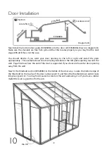
Page 33: ...dle with 25mm round head screws diagram 46 Slide the door glide onto the door guide bracket and then fix to the bottom of the door Keep the down leg of the guide in line with the inside edge of the do...

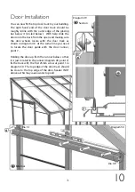
Page 34: ...eing installed on the left gable opening towards the wall Page 36 shows how the end of the track is supported if you choose to have the door opening away from the wall Now fit the threshold section EV...

Page 35: ...oor onto the track from the open end making sure the door wheels locate with the door track as shown in diagram 49 At the same time you need to locate the door guide with the door runner point 7 Holdi...

Page 36: ...y fix the middle screw to the track point 3 When fixing the end of the track at point 4 you will need to use 1 x D221 when glazing with cedar bar capping and 2 x D221 with aluminium bar capping Adjust...

Page 37: ...ernal EV0110 EV0291M Diagram 54 External Now offer up the staple EV0292M to the door and close the door until it locates correctly with the hasp Holding the staple in this position open the door again...

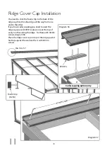
Page 38: ...ap first this should go all the way from one end to the other If you have cedar capping you need to used the ridge cap spacer EV0374 place one at the top of every roof bar along the ridge Fix these wi...

Page 39: ...nd fix it with a 50mm screw and rawl plug The location of the fixing point is entirely dependant on the donor wall look for the best place to get a secure fixing You can run a bead of silicone along t...

Page 40: ...ke a 610mm x 610mm pane of glass and locate this in the vent hinge Before lowering this down completely slot the glass stops onto the open edge Cedar capping part number EV0151 When in position you ca...

Page 41: ...n the roof If you have the aluminium ridge cover then use the 13mm self taping screws if it is the cedar ridge cover just use the standard 19mm screws Secure one of the vent stops D220 at one end of t...

Page 42: ...secure the top arm of the autovent to the roof vent do this with the roof vent in the closed position so that you get the bracket in the correct position Adjust the lower arm on the slam rail until t...

Page 43: ...ould secure in the cloaking strip diagram 52 When you are happy with the final position of your greenhouse and all the sides are vertical and square you can fix the greenhouse to the ground Use brown...

Page 44: ...is fixed you can now secure the gutter through the other fixing points Fit the gutter outlet to the downpipe and then to the gutter again using clear silicone if necessary It is a good idea to suppor...

Page 45: ...2 D234 Lean to Foam 7 meters black 2 2 2 2 2 Description Alton Evolution SIX Lean to Gable Box Product Code Description Quantity EV0006 Cill Front Gable 6ft 8ft wide 630mm 2 EV0010 Cill Rear Gable 6ft...

Page 46: ...EV0018 Cill Side 12ft long 3736mm 1 EV0234M ALU Gutter 4ft 1270mm MOSS 1 EV0235M ALU Gutter 6ft 1900mm MOSS 1 EV0236M ALU Gutter 8ft 2530mm MOSS 1 EV0237M ALU Gutter 10ft 3160mm MOSS 1 EV0238M ALU Gu...

Page 47: ...MOSS 1 1 1 1 1 EV0390M LT 6 left gable capping 2530mm MOSS 1 1 1 1 1 EV0391M LT 6 right gable capping 2530mm MOSS 1 1 1 1 1 15 Description Alton Evolution SIX Lean to Cedar Capping Product Code Descr...

Page 48: ...talled in the greenhouse you can replace the manual handle with the automatic unit First of all remove the screw to release the arm diagram 57 Next Remove the handle from the frame of the louvre diagr...

Page 49: ...ener to the frame using the 2 plates and 2 washers diagram 61 You should have either 19mm or 25mm screws spare from the greenhouse frame for this Once fixed in place attached the louvre arm to the ope...

Page 50: ...50 Notes...

Page 51: ...51 Notes...

Page 52: ...Alton Greenhouses TGP Ltd Blythe Park Cresswell Stoke on Trent ST11 9RD Telephone 01782 385 409 www Altongreenhouses co uk sales altongreenhouses co uk...

Reviews: