Altocraft 07385000 Operator'S Manual Download Page 22

ENGLISH

22

CMS212S

OPERATION

MAINTENANCE

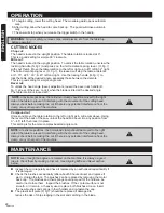
5. To begin cutting, lower the cutting head.  The movable guard opens automati-

cally.

6. After cutting, allow the head to come back up.  The guard will close automati-

cally.

7.  The saw will stop when you release the trigger switch in the handle.

WARNING:


For your safety, remove chips, small pieces, etc. from the table top 

before operation.

CUTTING MODES


Chop cut:

The head is locked in the upright position.  The table rotation is locked at 0°.  

This is a good setting for simple 90° crosscuts. 

Mitre cut:

The head is locked in the upright position.  To unlock the table rotation, unscrew the 

locking handle (

N, fig.1)

 and press on the mitre detent spring lever  (

O, fig.1

with your thumb  Move the table rotation to the left or right up to 45° left & 52° right. 

The mitre detent spring lever  (

O, fig.1

), if released, will stop the table at detents 

at 0°, 15°, 22.5°, 30°, & 45° left and right.  Use the locking handle (

N, fig.1

) to 

lock the table at the desired angle, especially those between the detents.

This is a good setting for simple angle cuts.

Bevel cut:

To unlock the head angle (bevel) adjustment, loosen the bevel lock handle (

D, 

fig.1

) at rear of the saw.  Lock it when the blade is tilted at the desired angle.  

The table rotation is locked at 0°.

NOTE

at extreme positions, the hold-down clamp should be moved to the right 

side of the table to prevent it interfering with the movement of the cutting head.  

Always check before making the cut if there is any potential interference from the 

clamp or any other part of the machine

Compound cut:

Unlock and move the table rotation to the left or right as in mitre cuts above. Using 

the lever at the back of the saw, unlock the head and bevel it to any position from 

0° – 45° left, then lock it in place.

This setting is for the more complex beveled angle cuts.

NOTE

at extreme positions, the hold-down clamp should be moved to the right 

side of the table to prevent it interfering with the movement of the cutting head.  

Always check before making the cut if there is any potential interference from the 

clamp or any other part of the machine

NOTE: 

even though the angles are marked on the machine, it is always a good 

idea to check them by making a trial cut.  See Aligning Mitre and Bevel section

below.

 

Inspect the cord regularly and have it replaced by an authorized repair facility if 

it is damaged. 

 

Check the brushes occasionally (after about 50 hours of use) and replace if 

worn.  Unplug the tool.  The brushes can be replaced by removing the motor 

back cap.  The brushes and their springs could jump out of the holders- be 

careful not to lose them.  Inspect the brushes.  If the contact surface is not 

smooth, or it is worn, or heavily used, replace both brushes at once. Insert  

the new brushes and springs in their holders and re-fasten the cap. 

 

The plastic kerf plate (

K , fig.1

) should be replaced if damaged to 

reduce the risk of chips lodging in the slot and catching in the blade.

Summary of Contents for 07385000

Page 1: ...num ro sans frais Our Customer service staff is available to help you For help with product assembly to report damaged or missing parts or for any other information about this product please call our...

Page 2: ...ou d quipement lectriques afin de r duire les risques de blessure Lisez ce guide en entier avant d utiliser cet outil CONSERVEZ CES INSTRUCTIONS 2 CMS212S LISTE DES COMPOSANTES R GLES DE S CURIT POUR...

Page 3: ...ultipli si votre corps est mis la terre 6 N exposez pas l outil lectrique la pluie ou l humidit Si de l eau entre dans l outil les risques de choc lectrique sont multipli s 7 Manipulez le cordon d ali...

Page 4: ...de l outil Ces mesures de s curit pr ventives r duisent les risques de d marrage accidentel de l outil 19 Rangez l outil non utilis hors de port e des enfants ou des personnes non famili res avec l o...

Page 5: ...la scie un nouvel angle v rifiez que la scie ne coupera pas dans la plaque de coupe le guide arri re ni toute autre partie de la scie cause d un mauvais ajustement UTILISEZ TOUJOURS LA CL POUR LAME po...

Page 6: ...lage ressort U g 2 situ du c t droit derri re le moteur Tournez le d un quart de tour jusqu ce que l axe de l arbre se repose dans la petite rainure pour assurer que le bouton reste sorti Pour d verro...

Page 7: ...ide Ins rez l arbre de la serre de retenue dans l ouverture du guide L g 1 et serrez la vis S g 2 l arri re du guide pour xer l arbre 2 R glez la position de la fourche de la serre de retenue selon l...

Page 8: ...e boulon d arr t et retirez la poign e de la position inf rieure Avant de mettre la scie en marche assurez vous que la lame ne touche pas la pi ce couper ou l tau Appuyez lentement sur la poign e pend...

Page 9: ...e pi ce de la scie risque d entrer en contact d interf rer avec la t te de coupe REMARQUE Bien que les angles soient marqu s sur la scie c est toujours une bonne id e de les v rifier en effectuant une...

Page 10: ...rrou de biseau l arri re 3 l aide du triangle de r glage en plastique assurez vous que la lame et la table forment un angle droit Si non 4 Utilisez une cl pour desserrer l crou de blocage et puis tour...

Page 11: ...la nouvelle lame de scie a un diam tre de 10 po 255 mm une capacit minimale de 6000 tr min et un trou d axe de 5 8 po 15 9 mm de diam tre 2 Lorsque vous installez une lame de scie assurez vous que les...

Page 12: ...fectueux sa discr tion Ce produit est garanti durant 12 mois s il est utilis de fa on normale Toute garantie est invalide si le produit a t utilis en surcharge ou de fa on non recommand e ou a fait l...

Page 13: ...le B Vis t te cylindrique phillips M4 x 10 Rondelle plate 4 Rondelle ressort 4 Pointeur du plateau tournant Morceau du plateau tournant Vis t te cylindrique phillips M4 x 16 Rondelle plate 4 Rondelle...

Page 14: ...14 CMS212S SCH MA SCHEMATIC DRAWING FRAN AIS ENGLISH...

Page 15: ...sher 4 Locking handle cover Locking handle Hex bolt M8 16 Nut M10 Saw blade side board Saw blade 225 Saw blade inner board Flat washer Cross flat head screw M4 10 Bearing clamp Cross panhead screw M5...

Page 16: ...t in serious personal injury WARNING When using electric tools machines or equipment basic safety precautions should always be followed to reduce the risk of fire electric shock and personal injury Co...

Page 17: ...he cord carefully Never use the cord to carry the tools or pull the plug from an outlet Keep cord away from heat oil sharp edges or moving parts Replace damaged cords immediately Damaged cords increas...

Page 18: ...maintained tools 22 Use only accessories that are recommended by the manufacturer for your model Accessories that may be suitable for one tool may become hazardous when used on another tool SERVICE 2...

Page 19: ...to bounce or kick back violently and could cause injury IF MAKING A CUT USING ONE HAND TO HOLD THE SAW ensure the free hand is clear of the cutting area 15 Amp 120 V 60 Hz motor No load speed 5 000 R...

Page 20: ...s Slide the table side extensions into the holes at the left and right of the table Tighten the table extension retainer screws B fig 1 to hold them in place Fit the dust bag over the dust port T fig...

Page 21: ...nt the hold down clamp on one side of fence Insert shaft of the hold down clamp into the mounting holes L fig 1 and tighten the hold down clamp retainer screw S fig 2 to fix shaft of hold down clamp 2...

Page 22: ...ing with the movement of the cutting head Always check before making the cut if there is any potential interference from the clamp or any other part of the machine Compound cut Unlock and move the tab...

Page 23: ...degree adjustment 1 Lower saw head to low position and lock it with the head lock button 2 Loosen the bevel lock handle U g 2 on the back of the saw 3 Check that the blade is perpendicular to the tab...

Page 24: ...om being raised or lowered See Fig 2 3 1 When replacing the saw blade make sure the new saw blade has a diameter of 10 255 mm minimum rating of 6 000 RPM and an arbor hole of 5 8 15 9 mm diameter 2 Wh...

Page 25: ...of any malfunction of your tool failure missing part etc please contact one of our service technicians at our toll free service line at 1 866 206 0888 from 8 AM to 6 PM Monday to Friday Eastern time...

Reviews: