background image

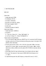
7. TEST PROCEDURE 

MOD-16H  

Instruments: 

1. signal generator: 8903b 

2. oscillograph: LS8106 

3. modulator: JMM-2200 

4: frequency recorder: EFC-3203A 

5. DC power supplier: 3303A. 

6. multi-meter 

7. frequency spectrum: E4403B 

Instruments Setting: 

1. signal generator: 1kHz/65mV. 

2. modulator: 

2.1. Tone set: H: Pass: 3K    L: Pass: 50K RANGE: 10 

2.2. AF set: H: Pass: 25    L: Pass: 15K RANGE: 50 

Test procedure and specification:

1. Turn on the power supply (press the ON/OFF key for 2 seconds), the LED indicator 

will light up, after the LCD show the battery and frequency status, the bright of LED 

indicator will be decreased. 

2. Test the sense power of PL2 on CH1, CH6, CH12 are above 5dBm, the sense 

power of PL1 is above 1dBm, the sense power of PL0 is above -5dBm, and the 

harmonics is below -45dBm. (note: the power of PL1/PL2/PL0 must have obvious 

variation) 

3. Input signal from MIC input terminal (shout), the modulator will have output. 

4. Tone test: Tone signal is in the range of 3KHZ±0.5KHZ, the frequency is in 

31~34KHZ. 

5. In standard range test the radio frequency, and permit the error in 

±2KHZ. 

- 16 -

Summary of Contents for MOD-16H Series

Page 1: ...MODEL MOD16H 16P ...

Page 2: ...CONTENT 1 INTRODUCTION 1 2 TECHNICAL SPECIFICATION 2 3 BLOCK DIAGRAM 45 4 SCHEMATIC DIAGRAM 6 5 WIRING DIAGRAM 9 6 PCB LAYOUT 11 7 TEST PROCEDURE 16 8 EXPLODED VIEW MECHANICAL PARTS LIST 20 9 BOM 24 ...

Page 3: ...hargeable battery design Selector for three different output levels depending of kind of receiver used LCD display Battery status display Mute function this function is very welcomed by Politicians Lock function to avoid miss action during a live performance 1 INTRODUCTION 1 ...

Page 4: ...кʼʳ T H D 1KHz 0 8 Modulation mode FM F3E RF output power 5 50mW adjustable 3 bands Dynamic Ї100dBʳ Tone frequency 30 33 KHz Current drain 100mA Max Deviation 35KHzʳ Battery AA type 2 Optional Nickel hydrogen battery charger Mic Capsule optional Dimensions Condenser or Dynamic Capsule 277 ӽˆˉˁˈ 10 9 ӽ1 44 Condenser or Dynamic Capsule 97mm ʳ 68mm ʳ 22mm 3 82 ʳ 2 68 ʳ 0 87 Weight 0 246Kg 0 082Kg 2 T...

Page 5: ...HESIZED Frequency response 50 Hz 15KHz 3dB Frequency stability 0 005 10шC 50шC T H D 1KHZ 0 8 Modulation mode FM F3E S N Ratio Ї90dB Dynamic Ї100dB RF sensitivity 100 dBm 30dB SINAD Audio output Unbalanced 6 3mm phone jack 750mV 35KHz deviation Balance output 1V 35KHz deviation Power supply DC15V 500mA AC 115V 230V 50 60Hz adaptor Dimensions 210 W 55 D 4 H mm 8 2 ʳ 6 1 ʳ ʳ 1 7 Weight 0 99Kg 3 ...

Page 6: ...O IC3 AMP IC55 2 1 AF FLITER IC59 3 3V REGULATOR IC2 3V REGULATOR 3 PIC16F74 Micro controler U132 LCD U130 DETE103067BEP Q2 Q15 CHARGE PUMP PLL BLOCK MT GT Mic IN RF B P F IC58 5V REGULATOR 3 3V IC1 PLL CONTROL IC58 Q53 DC CONVERTER RF POWER LEVEL DC9V IN PUT 5 5 3 MOD 16H 3 BLOCK DIAGRAM 4 ...

Page 7: ...IC55 AF AMP IC55 2 1 AF FLITER IC59 3 3V REGULATOR IC2 3V REGULATOR 3 PIC16F74 Micro controler U132 LCD U130 DETE103067BEP Q2 Q15 CHARGEPUMP PLL BLOCK MT GT M i cI N RF B P F I C58 5V REGULATOR 3 3V I C1 PLL CONTROL I C58 Q53 DC CONVERTER RF POW ER LEVEL DC9V I N PUT 5 5 3 MOD 16P 5 ...

Page 8: ...22uF 10V C10 103P C16 8P C3 47P C2 10P C1 47P C19 472P R4 4 7K CLK DA LE X1 12M HZ 3V T 3V D O 3VDO 3 GND GND GND LE DA CLK GND VC O 790 826M Hz GND 3 GND GND GND R17 18R R21 470R C20 1 8P R23 47R R28 2K C33 56P C34 2P C36 472P C29 1P C21 4 7P C25 472P GND VD1 BB142 C6 102P C22 10uF 10V T GND 1 2 3 4 5 6 7 8 9 10 11 12 13 14 15 16 I C1 M B15E03SLPFV C37 1P GND L69 10nH L70 10nH C83 3 3P R19 4 7K R...

Page 9: ...VSS 6 VDD 7 RB0 8 RB1 9 RB3 PGM 11 RA4 23 U132 PI C16F74 RC0 RC2 RC3 RC4 RC5 RE0 RE1 RE2 RA0 RD0 RD1 RD2 RD3 RD4 RD5 RD6 RD7 RB0 RB1 RB2 RB3 RB4 RB5 SEG1 5 SEG2 6 SEG3 7 SEG4 8 SEG5 9 SEG6 10 SEG7 11 SEG8 12 SEG9 13 SEG10 14 SEG11 15 SEG12 16 SEG13 17 SEG14 18 COM 1 4 COM 2 3 COM 3 2 COM 4 1 U130 RF_SM ALL_LCD 1 1 2 2 T8 M LB 160808 0080A N2 VI N D3 1SS355 R132 82K R133 82K R134 82K R131 82K R139 ...

Page 10: ...P C7 104P C5 47P 5 C38 10uF 10V T C39 10uF 10V T OUT G I N I C2 XC62FP3002 3VT C27 104P C28 104P GND OUTPUT3 3V C17 22uF 10V C10 103P C16 10P C3 47P C2 10P C1 47P C19 472P R4 4 7K CLK DA LE X1 12M HZ SC00398 3V T 3 GND GND GND LE DA CLK GND VC O 794 805M Hz GND 3 GND GND GND R17 18R R21 430R C20 1 8P R23 100R R28 1 8K C33 56P C34 2P C36 472P C29 1P C21 4 7P C25 56P GND VD1 BB142 C6 102P C22 47uF 7...

Page 11: ...1 2 3 4 A B C D 4 3 2 1 D C B A LCD CN1 CN2 CN3 CN4 UP 8P A MOD 800P UP 8P B red black negative spring leaf positive spring leaf aerial butt insert butt insert 5 WIRING DIAGRAM 9 MOD 16P ...

Page 12: ...3 2 1 D C B A 1 4 3 2 M i c M i c Vcc GI D GND connect two lines to condenser 3 4 in parallel connect red line connect guitar line connect white line connect ground line connect three lines to condenser3 4 in separate 10 ...

Page 13: ...PCB UP MIC Top Layer Top Overlay Top Solder PCB UP MIC Bottom Layer Bottom Solder 6 PCB LAYOUT MOD 16H 11 ...

Page 14: ...PCB UP 8H V2 Bottom Layer Bottom Overlay Bottom Solder PCB UP 8H V2 Top Layer Top Overlay Top Solder PCB UP 8H V2 Ground Plane PCB UP 8H V2 Power Plane 12 ...

Page 15: ...PCB UP 8P A Bottom Layer Bottom Overlay Bottom Solder PCB UP 8P A Top Layer Top Overlay Top Solder MOD 16P 13 ...

Page 16: ...PCB UP 8P B Power Plane PCB UP 8P B Ground Plane PCB UP 8P B Bottom Layer Bottom Overlay Bottom Solder PCB UP 8P B Top Layer Top Overlay Top Solder 14 ...

Page 17: ...PCB UP 8P MIC Bottom Layer Bottom Solder PCB UP 8P MIC Top Layer Top Solder 15 ...

Page 18: ...e ON OFF key for 2 seconds the LED indicator will light up after the LCD show the battery and frequency status the bright of LED indicator will be decreased 2 Test the sense power of PL2 on CH1 CH6 CH12 are above 5dBm the sense power of PL1 is above 1dBm the sense power of PL0 is above 5dBm and the harmonics is below 45dBm note the power of PL1 PL2 PL0 must have obvious variation 3 Input signal fr...

Page 19: ...g variation and check the display is normal or abnormal 8 Low voltage test when it is 2 0V 0 1V the display will appear the low voltage when the voltage is below 2V the unit will be closed automatically 9 Total consumption current when the power is in PL2 the consumption is below 125mA 10 Turn off the power supply press the ON OFF for 2 seconds the LED lights up after the LCD display CH the LED li...

Page 20: ...ey for 2 seconds the LED indicator will light up after the LCD show the battery and frequency status the bright of LED indicator will be decreased 2 Test the sense power of PL2 on CH0 CH50 CH99 are above 5dBm the sense power of PL1 is above 2dBm the sense power of PL0 is above 4 5dBm and the harmonics is below 45dBm Note the power of PL1 PL2 PL0 must have obvious variation 3 Input signal from MIC ...

Page 21: ...g variation and check the display is normal or abnormal 8 Low voltage test when it is 2 0V 0 2V the display will appear the low voltage when the voltage is below 1 8V the unit will be closed automatically 9 Total consumption current when the power is in PL2 the consumption is below 125mA 10 Turn off the power supply press the ON OFF for 2 seconds the LED lights up after the LCD display CH the LED ...

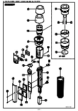
Page 22: ...8 EXPLODED VIEW MECHANICAL PARTS MOD 16H 20 ...

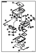
Page 23: ...MDO 16P 21 ...

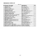
Page 24: ...V1 0 1 11 ND00593 wind proof sponge RS ij38 ij43 1 33 UP 83H black_V1 1 1 12 NI03851 rubber coil RS ij50 5 7 black_V1 0 1 13 MK00099 leaf spring battery 10 15 12 negative_V1 0 14 MG00626 screw RS M2 10_V1 0 1 15 MI02866 separating shade top cover 0 2t 23 5 29 5 2 4_V1 2 1 16 MI02865 separating shade top cover 0 2t 23 5 29 5 2 4_V1 3 1 17 NI04078 tail tube ij37 120 black_V1 0 1 18 MH01978 MIC socket UP...

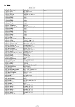
Page 25: ... T 1 8 NI03588 battery holder 20 7 32 5 68 5 black_V1 0 1 9 NI03586 battery switch 4 5 10 7 14 5 black_V1 0 1 10 NI03587 battery switch 2 12 19 black_V1 0 1 11 NI04126 key 5 4 9 24 black_V1 0 1 12 NI03584 fixed board 1 16 9 19 5 black_V1 0 1 13 MG00626 screw M2 10_V1 0 14 MG00695 pillar copper ij3 7 ij4 7 4 8_V1 0 1 15 NI04232 cushion 14 6 27 8 0 3t_V1 0 1 16 MK00098 spring clamp ij1 5 11 48 2 68 5mm...

Page 26: ...RS UP 8H 13 4 113 5 black_V1 1 27 NI03466 tube RS UP 8H ij20 6 48 8_V2 0 28 MD00777 up down steel net combination AU 800H ij50 62_V1 0 29 HG00176 buzzer PB 09N23P 03 30 HA01837 wire RS 43mm black L3R3 31 HA01847 wire RS 37mm red L3R3 32 HK05722 magnetic head DM 38 33 MH01978 MIC socket UP 8H ij38 36 DM 38 _V1 0 34 HA01781 wire RS 70mm L2R2 35 HA01782 wire RS 70mm L2R2 36 NI03595 caushion UP 8H ij35 1 ...

Page 27: ...C1608C0G1H010CT TDK C29 C37 C56 C81 C82 C84 C153 83 CI00079 SMD ceramic capacitor 0603 1 8PF 50VC0G 0 25PF C1608C0G1H1R8CT TDK C8 C20 84 CI00080 SMD ceramic capacitor 0603 2 2PF 50VC0G 0 25PF C1608C0G1H2R2CT TDK C73 85 CI00082 SMD ceramic capacitor 0603 3 3PF 50VC0G 0 25PF C1608C0G1H3R3CT TDK C23 C72 C74 C83 86 CI00084 SMD ceramic capacitor 0603 4 7PF 50VC0G 0 25PF C1608C0G1H4R7CT TDK C16 C14 C21 ...

Page 28: ...D fixed resistor 1 10W 2 2Kȍ 5 0603 R34 R60 R62 R80 R82 R88 R130 133 RD00091 SMD fixed resistor 1 10W 3 3Kȍ 5 0603 R20 R26 134 RD00093 SMD fixed resistor 1 10W 4 7Kȍ 5 0603 R3 R4 R5 R15 R16 R35 R36 R46 R55 R93 135 RD00095 SMD fixed resistor 1 10W 5 6Kȍ 5 0603 R68 R96 R19 136 RD00099 SMD fixed resistor 1 10W 8 2Kȍ 5 0603 R42 137 RD00101 SMD fixed resistor 1 10W 10Kȍ 5 0603 R12 R25 R31 R32 R43 R45 R...

Page 29: ...cuit SA575DTBR2 TSSOP20 ON IC3 172 CI00077 SMD ceramic capacitor 0603 1 2PF 50VC0G 0 25PF C1608C0G1H1R2CT TDK C31 173 RD00306 SMD fixed resistor 1 10W 20Kȍ 5 0603 R78 174 MI02867 separating shade RS ACT UP 8H 0 2t 4 8 23 1 29 1_V1 4 175 MJ01314 tinplate 0 2t 40 1M 1M 0 5KG _V 1 0 176 MI03098 separating shade RS ACT UP 8P 0 2t 2 8 14 2 14 3_V1 5 177 MJ01314 tinplate 0 2t 40 1M 1M 0 5KG _V 1 0 178 A...

Page 30: ...V1 0 26 AE00055 solvent solvent 27 AE00056 paint RS 2745 28 NI03584 fixed board RS ABS UP 8P 0 9 16 9 19 5 black_V1 2 29 MG00417 screw M2 6 B type 30 MG00626 screw RS M2 10_V1 1 31 MG00695 copper pillar ij3 7 ij4 7 4 8_V1 0 32 NI04232 caushion RS UP 8P 14 6 27 8 0 3t_V1 1 33 HF00052 antenna RS YH940805 ij4 82 4mm 34 NE15891 lable MOD 16P F7 798 827 ALTO_V1 0 35 NI00034 membrane 0 045 1M 36 NH00014 bo...

Page 31: ...r 12 000MHZ X1 81 HC00714 DC jack LD 0211 1 3 CN5 82 HK05771 PC board P UP 8P B_F7 SMD 83 HB01804 PCB RS UP 8P B_VER060121 84 SF00005 SMD transistor RS ACT 2SA1797Q SC62 ROHM Q15 85 SF00042 transistor XP151A13A0MR SOT23 TOREX Q4 Q53 86 SF00010 SMD transistor RS ACT 2SC2412K SC59 ROHM Q2 Q5 Q61 87 SF00004 SMD transistor RS ACT 2SA1036K SC59 ROHM Q14 88 SF00050 transistor XC9103D093MR SOT25 TOREX IC...

Page 32: ... L5 140 CO00076 SMD chip inductance RS 18nH 5 MLG1608B18NJT TDK L56 141 CO00067 SMD chip inductance RS 10nH 5 MLG1608B10NJT TDK L58 L59 L60 L61 L69 L70 L71 142 CO00069 SMD chip inductance RS 15nH 5 MLG1608B15NJT TDK L3 L6 L9 L54 143 CO00051 SMD chip inductance 1uH NLV25T 1R0J TDK L7 L65 144 CO00088 SMD chip inductance RS 1 0uH 10 MLF1608A1R0K TDK L10 145 CI00132 SMD ceramic capacitor 0603 2PF 50V ...

Page 33: ... C1608C0G1H560JT TDK C9 C25 C33 C35 C41 C57 C65 C70 180 CI00228 SMD ceramic capacitor 0603 0 001uF 50V C0G 5 C1608C0G1H102JT TDK C6 C40 C53 C58 C60 C63 C114 C116 C128 C152 181 CI00222 SMD ceramic capacitor 0603 330PF 50V C0G 5 C1608C0G1H331JT TDK C147 C151 182 CO00124 SMD chip inductance RS 0603 180nH 5 MLG1608SR18JT TDK L1 L66 L67 183 RD00112 SMD fixed resistor 1 10W 56Kȍ 5 0603 R58 184 CO00105 S...

Reviews: