User's Manual
LTO
R
www.altoproaudio.com
Version 1.0 January 2006
English
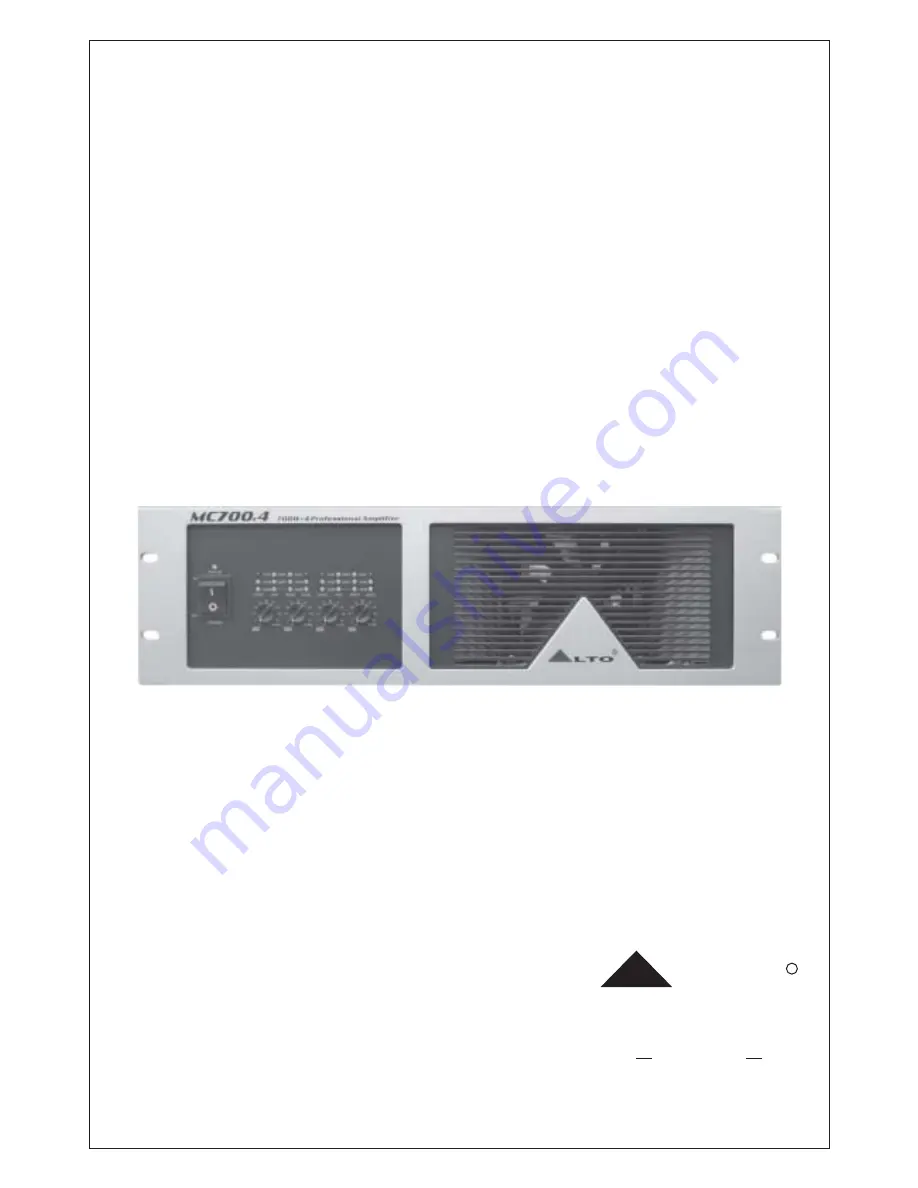
MC700.4
FOUR CHANNELS POWER AMPLIFIER
Page 1: ...User s Manual LTO R www altoproaudio com Version 1 0 January 2006 English MC700 4 FOUR CHANNELS POWER AMPLIFIER ...
Page 2: ...t away from naked flames Read these instructions Follow all instructions Keep these instructions Do not discard Heed all warnings Only use attachments accessories specified by the manufacturer Do not tamper with the power cord or plug These are designed for your safety Do not remove Ground connections If the plug does not fit your AC outlet seek advice from a qualified electrician Protect the powe...
Page 3: ...ers in Italy Netherlands United Kingdom and Taiwan The core of our digital audio products is a sophisticated Software Team for the many years Following this idea we create our products and we will create the new ones From our side we guarantee you and we will guarantee you also in future the best quality the best fruits of our continuous researches and the best prices Nothing else to add but that ...
Page 4: ...CAUTION FOR APPLICATION BLOCK DIAGRAM TECHNICAL SPECIFICATIONS WARRANTY 10 11 12 13 TABLE OF CONTENTS 1 INTRODUC ION T 4 2 FEATURES 4 3 CONTROL ELEMENTS 5 4 5 6 7 8 4 INSTALLATION APPLICATION 8 8 9 3 ...
Page 5: ...tees total reliability and a trouble free use even in the most demanding conditions We believe the MC700 4 not only look great but provide a perfect performance what you get is unprecedented performance at an incredibly attractive price 2 FEATURE Innovative design and high stability power amplifier Fan cooled high power amplifier in 19 3U size 4 independent channels with separate protection system...
Page 6: ... corrected the protection systems deactivate automatically this indicator goes out and normal amplifier operation is resumed Output Limiter LED Set the clip limit switch at ON position the yellow LED lights up when the unit is limiting the output signal Level Control This pot provides smooth level changes control Fan The unit is equipped with two fans which can accelerate the flow of air to lower ...
Page 7: ...all dip switches these small dip switches from1 to 5 control one channel the rest ones 6 10 control the other channel You can choose the right mode setting you need via these small dip switches Take the dip switch of channel 1 and channel 2 for example Channel 3 and channel 4 are the same as channel 1 and channel 2 STEREO MODE 1 2 3 4 5 6 7 8 910 Output Mode Selector This unit provides three outpu...
Page 8: ...es down you will choose 75Hz low cut filter 12 14 13 35Hz FILTER FILTER OFF FILTER OFF 35Hz FILTER FILTER ON 75Hz FILTER 75Hz FILTER FILTER ON 1 4 5 6 7 10 Please refer to chapter 5 for the connection of loads in detain BRIDGE MODE 1 2 3 4 5 6 7 8 910 Output Terminal You can output the powered signal by the specific output connectors according to the actual application circumstance Caution turn of...
Page 9: ...S Ch4 Ch3 Ch4 CH3 CH4 BRIDGE MONO BRIDGE MONO CH2 CH1 INPUTS AC INPUT SERIAL MODEL Apparaten skall anslutas till jordat uttag nar den ansluts till ett natverk BREAKER OUTPUTS Channel 2 Channel 1 Channel 1 4 INSTALLATION 4 1 Mains connection Caution To reduce the risk of electric shock do not perform any servicing other than contained in this manual unless you are qualified to do so Please turn off...
Page 10: ... Channel 1 1 2 3 4 5 6 7 8 9 10 1 2 3 4 5 6 7 8 9 10 CH1 MODE SWITCHES CH2 INPUTS CH1 CH2 CH3 MODE SWITCHES Ch4 Ch3 Ch4 CH3 CH4 BRIDGE MONO BRIDGE MONO CH2 CH1 INPUTS AC INPUT SERIAL MODEL Apparaten skall anslutas till jordat uttag nar den ansluts till ett natverk BREAKER OUTPUTS Channel 2 Channel 1 PARALLEL MODE 1 2 3 4 5 6 7 8 910 Channel 1 9 5 3 Operate MC700 4 In Bridge Mode In this mode the c...
Page 11: ...the speaker s input capacity Po I R I Po R 2 Po W Speaker s continuous input capacity noise or RMS R Speaker s nominal impedance I A Required fuse capacity Output Fuse Speaker System 6 CAUTION FOR APPLICATION 6 1 General Application instruction the following instructions describe the common ways to install your MC700 4 power amplifier into a sound application system First turn off power switch bef...
Page 12: ...11 7 BLOCK DIAGRAM 7 BLOCK DIAGRAM PT MC700 4 ...
Page 13: ... 40 32dB 1Vrms 10 Vrms 22dB 10Kohms unbalanced 20 Kohms balanced Front AC Switch Ch1 Ch4 Gain Knobs Rear MODE SWITCHS Power On Blue LED Protection Green LED LIMITER Yellow LED Clip Red LED Parallel input Yellow LED Bridge Yellow LED Level Green LED 20 and 10dB Connectors each channel Input Terminal Block Output Screw terminal Barrier Block Power supply cooling Load protection Dimensions Net weight...
Page 14: ...TO of 1 year from the purchase date if you have completed the Warranty Registration Card in time 3 3 During the warranty service may repair or replace this product at its own option at no charge to you for LTO parts or for labor in accordance with the right side of this limited warranty 3 4 This warranty does not apply to the damages to this product that occurred as the following conditions Normal...
Page 15: ...alto altoproaudio com Fax 886 4 22346757 c All rights reserved to ALTO All features and content might be changed without prior notice Any photocopy translation or reproduction of part of this manual without written permission is forbidden Copyright 2005 SEIKAKU GROUP SEIKAKU TECHNICAL GROUP LIMITED NF02316 1 0 ...