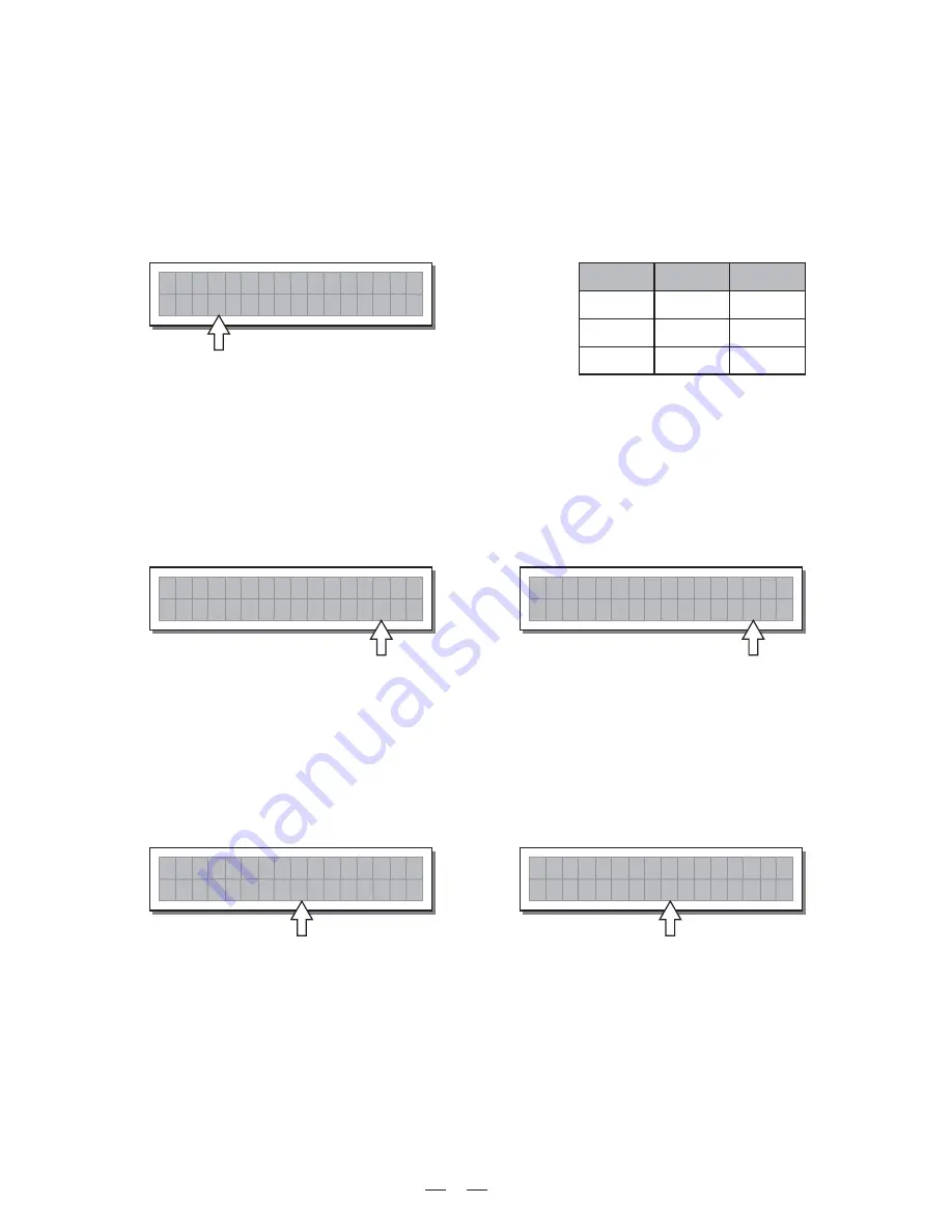
background image

21

5.4 UTILITY Menu

IMPORTANT!

Enabling the LIMITER on a specific output also changes the way in which the level is displayed

on the corresponding

In fact, the level shown on this ladder is no longer the "absolute" output level,

LED ladder:

but the level of the signal at -24dB, -12dB, -6dB compared to the

(orange

LED), no

LIMITER's threshold

LIMIT

matter what the threshold value is.

This menu comprises a series of submenus that allow to set a series of system options and access certain utilities,
such as the control of the protection against accidental or unauthorized changes:

b. Reaction Times

Allows to choose between 3 types of Limiter reaction speed.
In fact, these are attack and release times that are optimised so that the Limiter reacts more or less rapidly
when the signal exceeds or drops below the threshold:

Fast

Normal

to mid frequencies or full-range systems.

Slow

suited to outputs dedicated to low frequencies.

signal unchanged.

The editing values are within the following ranges:

+19.8dBu ~ -10dBu, with 0.2dBu steps
7.574V ~ 0.245V with variable steps

The Off value disables the LIMITER, whereas any other value enables it.

LIMITER

FAST

NORMAL

SLOW

ATTACK

RELEASE

1 ms

10 ms

8 ms

80 ms

45 ms

450 ms

O P 1

f

f

O

s

a

F

t

O P 1

8

5

o

l

S

w

.

O P 1

f

f

O

o

l

S

w

short times, suited to rapid Limiter operation. Normally more suited to outputs dedicated to high
frequencies.
intermediate times, suited to the majority of applications. Normally more suited to outputs dedicated

long times, suited to avoiding rapid repeated level jumps (pump effect). Normally most

Allow to set the level above which the Limiter intervenes (limiting the signal) and below which it leaves the

The measurement unit can be chosen with the Lim. Thresh. Unit function (

menu

submenu).

UTILITY

- Units

o m

L i m

C

P

L i m .

L i m .

L i m .

o m

L i m

C

p

o m

L i m

C

p

c. Threshold

d. Ratio

Allows to set the compression ratio, that is to say how the signal exceeding the threshold has to be reduced.
The editing values are the following: Lim. 20.0 10.0 8.0 6.0 5.0 4.0 3.5 3.0 2.5 2.0 1.7 1.5 1.3 1.1.

The "Lim." Value corresponds to the maximum compression ratio (all the signal exceeding the threshold is cut)
and in this condition the processors acts as a LIMITER.

The other values allow to reduce the signal with a ratio from 1:20.0 (high compression) to 1:1.1 (low compression)
in order to obtain different compression effects according to the kind of signal and to the kind of application.

O P 1

o

l

S

w

O P 1

f

f

O

o

l

S

w

. 5

2

L i m .

o m

L i m

C

p

o m

L i m

C

p

f

f

O

Summary of Contents for MAXIDRIVE2.3+

Page 1: ...MAXIDRIVE2 3 2 WAY STEREO DIGITAL CROSSOVER User s Manual LTO R www altoproaudio com Version 1 5 October 2005 English ...

Page 2: ...uct away from naked flames Read these instructions Follow all instructions Keep these instructions Do not discard Heed all warnings Only use attachments accessories specified by the manufacturer Do not tamper with the power cord or plug These are designed for your safety Do not remove Ground connections If the plug does not fit your AC outlet seek advice from a qualified electrician Protect the po...

Page 3: ... create the new ones From our side we guarantee you and we will guarantee you also in future the best quality the best fruits of our continuous researches and the best prices Thanks for choosing MAXIDRIVE2 3 2 Way Stereo Digital Crossover and thanks for choosing one of the results of LTO AUDIO TEAM job and researches Our AXIDRIVE2 3 2 Way Stereo Digital Crossover is the result of many hours of lis...

Page 4: ...34 9 WARRANTY 35 4 2 Adjust The Input Signal 3 5 THE MENU MAP CONFIGURATION DESCRIPTION 10 5 1 Preset Menu 5 2 Delay Menu 5 3 Edit Menu 5 4 Utility Menu 6 CONNECTIONS 28 7 APPLICATION 28 7 1 Factory Preset Configuration 7 2 Organization 4 3 First Setup 4 4 System Configuration 4 5 Number of Presets 4 6 Type of Preset 4 7 Name of The Preset 4 8 Preset Modifications 4 9 System Protection ...

Page 5: ... of the 8 5 10 9 6 7 4 3 2 1 1 MODE Key The button allows you to select four modes PRESET DELAY EDIT and UTILITY Pressing MODE repeatedly to reach to the required menu and the corresponding LED will light up You can edit the parameters of the selected menus If none of the menu LEDs is lit the Display shows the name of the current PRESET and no parameters can be modified 5 PREV NEXT Key Each menu c...

Page 6: ...the level of the signal at 24dB 12dB 6dB compared to the limiter threshold indicated by the orange LIMIT LED 12 AC Inlet and Fuse Holder 13 Power Switch The switch is used to turn the main POWER on and off Note before turning on the unit please make sure the amplifiers of the sound system are off to avoid the annoying and sometimes dangerous signal peaks CAUTION If there is something wrong with th...

Page 7: ... the following parts carefully And the system Will enter into default status showing the main operating information on the display A 1 3 B 2 4 2 F 2 x 2 W Load the containing the you ve found Factory PRESET configuration Press the Key until the menu LED lights up MODE PRESET The display will show the page Load PRESET Set all the MAXIDRIVE2 3 outputs in MUTE status LEDs lit by pressing the relative...

Page 8: ...ng parameters in order shown Output Pol Polarity of the outputs Xover Crossover frequencies separation of the speaker channels Output Delay Alignment of the speaker enclosure components Output Gain Levels of the outputs Use the to change the gain value and watch the level of the signal on the LED ladders until the ideal values DIAL are reached Then use the and keys to access to the page if there i...

Page 9: ...ollowing functions Output EQ Output equalizers Output Limiter Output limiters Note In this first phase of setting up your sound system the adjustment of these functions which if not Indis pensable during installation can wait But do remember that adjusting the equalizers can also affect the signal level So if considerable equalization changes are made remember to check and adjust the output levels...

Page 10: ...pect to the stored in the PRESET shown Practically speaking this indication means that the changes made to the PRESET have not been stored Note once it has been enabled the indication remains even if the original values are reset manually The indication disappears as soon as the PRESET is saved or as soon as a new PRESET is loaded includ ing this same PRESET In other words the indication disappear...

Page 11: ... PRESETS Factory PRESETS L o a d 2 F 2 x 2 W P r e s e t L o a d U P r e s e t 6 4 D e f a u l t A 1 3 U 6 4 D e f a u l t B 2 4 Factory programmed storage Factory PRESETS can be used normally temporarily modified but can t be cancelled overwritten or permanently modified Factory PRESETS contain some specific settings for certain types of enclosures and all the system s usable configurations For t...

Page 12: ...up position on the first of the twelve character spaces available At this point If you decide to accept and confirm the name suggested press ENTER If you want to abort procedure for example because you ve chosen the wrong memory area and Naming return to Store PRESET procedure press ESC S t o r e 2 U P r e s e t S t o r e 3 U P r e s e t Use to reach the memory area in which the PRESET is to be sa...

Page 13: ...number of the parameters and how they are presented varies according to the configuration of the PRESET and according to and settings Ganging Units UTILITY menu In fact these pages only show the parameters that can actually be used in the most suitable form of editing Parameters Input Delay delays the signal of an input or the sum of the inputs before sending it to the routing system In this way a...

Page 14: ...ents 5 2 1 Input Delay Use this menu page to adjust the delay lines of Input A Input B and SUM The values can be set in the following ranges The measurement unit can be chosen with the function menu submenu Delay Unit UTILITY Units 5 2 2 Output Delay Use this menu page to adjust the delay lines of outputs 1 2 3 and 4 IN A ADC unit m mm ms range step 0 0 900 0 0 5 0 900000 7 0 2621 1 INPUT DELAY us...

Page 15: ...show the parameters that can actually be used in the most suitable form of editing Parameters Input Gain Parameters Input EQ Parameters Xover Parameters Output EQ Parameters Output Gain Parameters Output Pol Parameters unit m mm ms range step 0 0 100 0 0 5 0 100000 7 0 291 1 OUTPUT DELAY us 0 291271 21 OUTPUT DELAY Components Loudspeaker Alignment 1 Delayed Virtual Alignment 2 Delayed Virtual OUTP...

Page 16: ...orm via the PREV and NEXT keys use the DIAL to set the value for these parameters The attack can be varied from 0 5 100mS with 0 5mS step The release is in the range 0 01s 4 00s with0 1s step The threshold is in the range 80 0dB 8dB with 0 5dB step The range is in the 80dB 0dB with 0 5dB step I N A B G A T E o f f I N A B G A T E o f f A T 1 0 m S R L 0 5 0 S T H R 6 0 0 R G 8 0 0 5 3 3 Input EQ I...

Page 17: ... curve and Notch filter or the cutoff frequency of Shelv ing curves Allows to choose among Peaking Low or High Shelving with a slope of 6 or 12 dB per octave and Notch filter Peaking Low Shelving High Shelving Notch a Type of Filter Peaking Low Shelving High Shelving Notch I N A E Q 1 5 0 k a e P 1 0 2 k 0 0 Each equalizer has 5 pages one for each filter showing the name of the input it affects an...

Page 18: ... crossover allows to divide the into segments that can be used by the individual section of a sound system for example audio signal High Mid Low X o v e r Peaking Notch d Gain Allows to control the boost or cut of the selected frequencies It s not used with the which has a fixed cut Notch Filter Peaking Low Shelving High Shelving I N A E Q 1 5 0 k a e P 1 0 2 k 0 0 ...

Page 19: ... 0 0 z H B e s 0 2 4 O P 1 L P F 1 k 4 6 z H T h r 0 u Each Xover has 2 slightly different pages one for each filter where the name of the output it affects and the type of filter are shown Low Pass Filter High Pass Filter The high pass filter allows all the frequencies above a specific frequency to pass whereas it cuts all the frequencies below it LPF HPF HPF LPF Signal segment obtained with the ...

Page 20: ...t 12 18 24 dB oct 12 24 48 dB oct 15 6Hz 16KHz 15 6Hz 16KHz 0 180 Stp 5 LPF HPF O P 1 L P F 1 k 0 0 z H T h r 0 u 8 1 5 3 5 Output EQ Output equalizer with 5 parametric filters Also called Channel EQ allows to alter the tone of each individual output The characteristics of quality and programmability are identical to those of the Input Equalizer and enable this unit to be used extremely effectivel...

Page 21: ...ays of speaker enclosures in the control of the interpolation between various enclosures or between sections of the same system 5 3 6 Output Gain Output level control Allows to adjust the signal level of each individual output Editing values are between 6dB 30dB with 0 5dB steps 5 3 7 Output Pol Controls the output s polarity Allows to invert the phase of the signal of individual outputs Editing v...

Page 22: ...CK RELEASE 1 ms 10 ms 8 ms 80 ms 45 ms 450 ms O P 1 f f O s a F t O P 1 8 5 o l S w O P 1 f f O o l S w short times suited to rapid Limiter operation Normally more suited to outputs dedicated to high frequencies intermediate times suited to the majority of applications Normally more suited to outputs dedicated long times suited to avoiding rapid repeated level jumps pump effect Normally most Allow...

Page 23: ... choose the measurement units to be used with certain functions a Delay Unit Used to set the measurement units in which Delays are expressed DELAY menu The options include meters millimeters milliseconds microseconds m mm ms us Delay Unit Lim Thresh Unit Units Temperature Unit U n i t s Measurement units for Input Delay D e l a y U n i t I n m s t u s O u Measurement units for Output Delay D e l a...

Page 24: ... U n i t a e r T e m P e u t F r U n i t a e r a Output Meters Used to decide whether to display the outputs signal before or after MUTE The options include Use this submenu to set a series of system options M i s c S e t u p PreMute the signal is always shown no matter what the MUTE status u t p u t M e t e r s P r e M t e O u PostMute the signal is only shown if the output isn t in MUTE u t p u ...

Page 25: ...grees Centigrade and F degrees Fahrenheit by means of the Temperature Unit function UTILITY menu Units submenu c Wake Up Allows to choose the mode in which MUTE functions are restored when the MAXIDRIVE2 3 is switched on The options include T e m p e r a t u r e 2 0 C T e m p e r a t u r e F 6 8 0 Mute when switched on the system automatically sets all the outputs in MUTE Normal when switched on t...

Page 26: ...PORTANT password The protection cannot be unlocked without the So write it down or at least choose a word that is easily remembered The password is made up of four alphanumerical characters obtainable using the and keys and editable with the DIAL After entering the password press ENTER Confirmation is only accepted if the cursor is positioned on one of the passwords four characters Note This allow...

Page 27: ...ame properties and or the same structure For example the right and left sections of a stereo system are similar as they are made up symmetrically of the same quantity and type of elements the same components for High Mid and Low frequencies G a n g i n g The practical use of the Ganging function consists in the possibility of editing with identical values the parameters of similar elements carryin...

Page 28: ... Outputs assume the same value with the just one operation For example even if the display shows that Input A B are ganged in the page with a certain parameter the value shown remains that of Input A until a new value is entered as Input B doesn t automatically assume the values of Input A This condition is used to avoid accidental or temporary enabling of the Ganging function from changing the va...

Page 29: ...et routing 2 WAY STEREO 2 WAY STEREO 2 WAY MONO with MONO SUB 2 MONO FULL RANGE OUT 3 WAY MONO with MONO SUB 1 MONO FULL RANGE OUT 4 WAY MONO 4 WAY MONO with B SUB 2 MONO FULL RANGE OUT 7 1 Factory Preset Configuration 6 CONNECTIONS The following diagrams show the schemes of the recommended cables and some connection examples referred to various system configurations Inputs A B 3 1 2 GROUND HOT CO...

Page 30: ...xamples will help you well use and connect the unit 1 3 2 4 1 2 3 4 A B SIGNAL POWER PWR OFF ON AC INPUT 14W 95 240V 50 60Hz FUSE 95 120V T500mAL 210 240V T315mAL INPUT A INPUT B 4 3 2 1 OUTPUTS Apparaten skall anslutas till jordat uttag nar den ansluts till ett natverk A102 PUSH 1 3 2 NEW TIDE PUSH 1 3 2 NEW TIDE CH A CH B CLIP SIG POWER ON OFF CLIP SIG PROT CH A CH B CLIP SIG POWER ON OFF CLIP S...

Page 31: ...OVER AUDIO MIXER SIGNAL POWER 1 2 3 4 4 3 2 1 A B MONO AUX L R SUB L R PWR OFF ON AC INPUT 14W 95 240V 50 60Hz FUSE 95 120V T500mAL 210 240V T315mAL INPUT A INPUT B 4 3 2 1 OUTPUTS Apparaten skall anslutas till jordat uttag nar den ansluts till ett natverk A102 PUSH 1 3 2 NEW TIDE PUSH 1 3 2 NEW TIDE CH A CH B CLIP SIG POWER ON OFF CLIP SIG PROT CH A CH B CLIP SIG POWER ON OFF CLIP SIG PROT LTO R ...

Page 32: ... DIGITAL CROSSOVER SIGNAL POWER HIGH MID LOW SUB 1 1 2 3 3 4 2 4 A B PWR OFF ON AC INPUT 14W 95 240V 50 60Hz FUSE 95 120V T500mAL 210 240V T315mAL INPUT A INPUT B 4 3 2 1 OUTPUTS Apparaten skall anslutas till jordat uttag nar den ansluts till ett natverk A102 PUSH 1 3 2 NEW TIDE PUSH 1 3 2 NEW TIDE CH A CH B CLIP SIG POWER ON OFF CLIP SIG PROT CH A CH B CLIP SIG POWER ON OFF CLIP SIG PROT LTO R R ...

Page 33: ...R AUDIO MIXER 1 2 3 4 1 2 A B HIGH MID LOW SUB PWR OFF ON AC INPUT 14W 95 240V 50 60Hz FUSE 95 120V T500mAL 210 240V T315mAL INPUT A INPUT B 4 3 2 1 OUTPUTS Apparaten skall anslutas till jordat uttag nar den ansluts till ett natverk A102 PUSH 1 3 2 NEW TIDE PUSH 1 3 2 NEW TIDE 3 4 CH A CH B CLIP SIG POWER ON OFF CLIP SIG PROT CH A CH B CLIP SIG POWER ON OFF CLIP SIG PROT LTO R R PROFESSIONAL HIGH ...

Page 34: ...CH A CH B CLIP SIG POWER ON OFF CLIP SIG PROT CH A CH B CLIP SIG POWER ON OFF CLIP SIG PROT LTO R R SIGNAL POWER MAXIDRIVE2 3 2 WAY STEREO DIGITAL CROSSOVER AUDIO MIXER 1 2 3 4 1 2 A HIGH MID LOW SUB PWR OFF ON AC INPUT 14W 95 240V 50 60Hz FUSE 95 120V T500mAL 210 240V T315mAL INPUT A INPUT B 4 3 2 1 OUTPUTS Apparaten skall anslutas till jordat uttag nar den ansluts till ett natverk A102 PUSH 1 3 ...

Page 35: ...nternal dynamics 40 bit Sampling frequency 48 kHz Features Configuration 2 WAY STEREO 2 3 4 WAY MONO Crossover Filters Type Bessel Butter worth or Linkwitz Riley Crossover Filters Slope 6 12 18 24 or 48dB per octave Delay Step 21 microseconds minimum Max Delay time 2621 ms inputs 291 ms outputs EQ filters Up to 40 maximum depending on the crossover slope EQ Gain 15dB variable in 0 5dB steps EQ Ban...

Page 36: ...d LTO of 1 year from the purchase date if you have completed the Warranty Registration Card in time 3 3 During the warranty service may repair or replace this product at its own option at no charge to you for LTO parts or for labor in accordance with the right side of this limited warranty 3 4 This warranty does not apply to the damages to this product that occurred as the following conditions Nor...

Page 37: ...313737 email alto altoproaudio com Fax 886 4 22346757 c All rights reserved to ALTO All features and content might be changed without prior notice Any photocopy translation or reproduction of part of this manual without written permission is forbidden Copyright 2005 SEIKAKU GROUP SEIKAKU TECHNICAL GROUP LIMITED ...

Reviews: