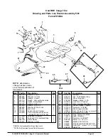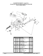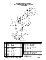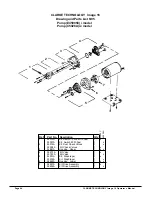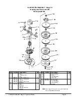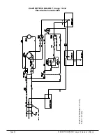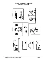
CLARKE TECHNOLOGY Image 16 Operator's Manual
Page 43
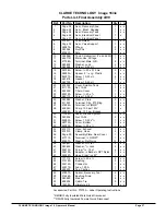
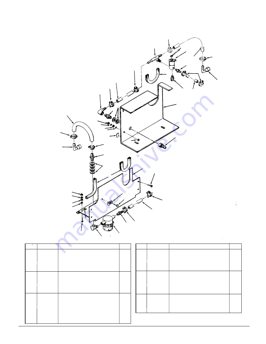
Ref.
Part No.
Description
Qty
1
722030
Clamp, Hose
10
2
30425A
Hose, Air 24"
2
3
170030
Hosebarb
1
4
68665A
Support, Valve
1
5
839204
Trim
3
6
85395A
Screw, ¼-20 x ½
4
7
980410
Washer, S.S.
4
8
170040
Elbow
1
9
697501
Reducer
1
10
737140
Quick Disconnect
1
11
35172B
Hose, 4½"
1
12
53619A
Hosebarb, Nylon
2
13
53050A
Strainer, Bowl (incl. #13a,b, c)
1
13a
58061A
Screen, Filter
1
13b
54369A
Gasket, Viton
1
13c
K
50018A
Bowl, Filter
1
14
85383A
Screw, 10-32
2
Ref.
Part No.
Description
Qty
15
980603
Washer, #10 Ext. Lock
4
16
920224
Nut, 10-32 Hex
4
17
962987
Screw, 10-24 x
3
/
8
1
18
692870
Elbow, Swivel
2
19
35147A
Hose 14"
2
20
59785A
Valve, Solution Flow
1
21
59016A
Tee
1
22
53617A
Elbow, ¼ NPT x
3
/
8
Hosebarb
1
23
50328A
Coupling, Female Q.D. shut-off
1
24
170863
Washer, flat
3
/
8
2
25
302101
Clip
1
26
77094A
Label, Ground Symbol
2
27
68668A
Plate, Rear, Cover
1
28
49068A
Wire, Ground
1
NOTE:
K
indicates a change has been made since the last
publication of this manual.
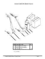
1
21
28
20
19
1
18
1
12
19
23
5
1
2
1
22
9
24
27
16
15
16
15
26
14
10
1
3
7
5
4
6
1
25
17
11
1
12
8
14
26
15
16
15
16
18
1
2
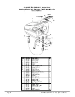
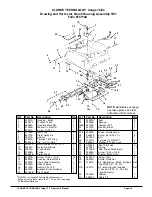
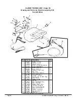
CLARKE TECHNOLOGY
Image 16
Drawing and Parts List, Valve Assembly 5/01
Form #19411A
13, 13a, 13b, 13c

