Alto EQU215 Service Manual Download Page 3

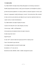
The EQU215-MKII V2 Graphic Stereo15-Band Equalizer is an extremely musical and 

flexible Graphic Equalizer, based on many years of experience and designed to provide a 

permanent precise equalization to musician, performer, and studio engineer. It can be used 

wherever is requested to modify the frequency “contour” of a sound and can offer a solution 

to many common sound problems and allows the user to use the creativity to obtain nice 

results in terms of sound characterization.   

The EQU215-MKII V2 Graphic Equalizer Features: 

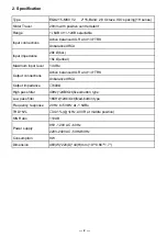
Constant Q circuitry with a 3% center frequency accuracy 

Control range +/-6dB/+/-12dB selectable 

Active balanced and unbalanced input and output connectors 

Variable input level control 

Signal clop pilot 

Ground “LIFT” switch to disconnect signal ground from chassis ground 

Power off automatic bypass function 

Line voltage selectable robust and compact design 

Mountable in a 19’’ rack unit (1U) 

Manufactured under QS9000, VDA6.1 certified management system 

1. Introduction

---  1  ---

Summary of Contents for EQU215

Page 1: ...www altoproaudio com Version 1 0 MODEL EQU215 MKII V2 Revised on Jan 2010...

Page 2: ...CONTENTS 1 Introduction 1 2 Specification 2 3 Block Diagram 3 4 Schematic Diagram 4 5 Wiring Diagram 9 6 PCB Layout 10 7 Test Procedure 14 8 Exploded View Mechanical Parts List 18 9 BOM List 20...

Page 3: ...user to use the creativity to obtain nice results in terms of sound characterization The EQU215 MKII V2 Graphic Equalizer Features Constant Q circuitry with a 3 center frequency accuracy Control range...

Page 4: ...alanced XLR and 1 4 TRS Unbalanced RCA Output impedance 600 High pass filter 40Hz 12dB Oct fixed button type Low pass filter 16KHz 12db Oct fixed button type Frequency response 20 Hz to 50kHz at 1 5dB...

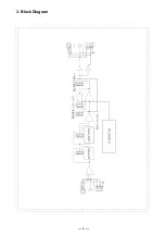
Page 5: ...3 Block Diagram 3...

Page 6: ...4 Schematic Diagram 4...

Page 7: ...5...

Page 8: ...6...

Page 9: ...7...

Page 10: ...8...

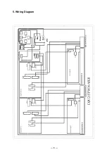
Page 11: ...Blue Black Red PT 5 Wiring Diagram 9...

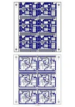
Page 12: ...6 PCB Layout 10...

Page 13: ...11...

Page 14: ...12...

Page 15: ...13...

Page 16: ...Connect the output of EQU215 MKII V2 to the input of AP Adjustment according to following procedures 1 Set the potentiometer of 15 band EQ in center set the input level at 0dB all buttons out 2 Turn i...

Page 17: ...sponse is as following 5 Adjust the input level so that the AP output is 0dB press the HI pass button and the frequency response is as following 6 Adjust the input level so that the AP output is 0dB p...

Page 18: ...12 adjust slide buttons to maximum and minimum measure the frequency response independently and the curve shall be as following 8 Turn off the AP input signal and set input level as maximum the AP se...

Page 19: ...is as following the maximum non distortion level is 28dBu 1dB and distortion is 1 10 Now the S N shall be no less than 110dB 11 Connect AP input and output to Channel 2 repeat steps 1 10 12 All slide...

Page 20: ...MODEL No EQU215 MKII V2 8 Exploded View Mechanical Parts List 18...

Page 21: ...2 12 ME00015 multicolored nut 3mm 1 13 MF00038 spring washer 4 7 1t 3 14 MF00048 outer gear washer 4 8 0 5t 3 15 ND00348 non woven cloth 0 35t 172 8 37mm 2016B_V1 0 2 16 NI00002 plastic nut Hex 7 16 G...

Page 22: ...61 assurance card RS C ALTO_V1 1 0031 NE05004 label ALTO PF_V1 2 0032 NE13266 label EQU215 MK _V1 0 0033 NI00002 plastic nut RS 7 16 G20 15 4 8 0034 NF01783 instruction English EQU MK SERIES ALTO_V1 2...

Page 23: ...09 RA01111 fixed resistor 1 4W 100K R16 R19 R21 R22 0010 CB00242 electrolytic capacitor 22uF 35V 5 11mm C1 C2 C3 C4 C5 C6 C8 C13 C40 C41 C46 C19 C22 0011 CB00235 electrolytic capacitor 100uF 25V 6 11m...

Page 24: ...100V 3 C21 C22 C23 0006 CH00018 laminated capacitor 0 1uF 50V Y5V C1 C2 C3 C4 C5 C6 0007 CC00060 mylar capacitor 0 1uF 100V 3 C31 0008 CF00142 metal film capacitor MSC 1 0uF 63V 5 CASE07 C122 0009 CC...

Reviews: