COMbIThERM® ES SERIES
•
ELECTRIC
INSTALLATION MANUAL #MN-28897 •
13.
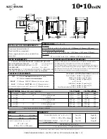
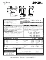
19-1/2"
(495mm)
12-5/16"
(312mm)
9-9/16"
(242m
m)
35-7/8" (910mm)
33-7/8" (860mm)
33" (837mm)
2" (50mm)
35-11/16" (905mm)
25"
(635mm)
7-9/16"
(191mm)
5" (126mm)
Water Drain
(Rear)
Steam
Vent
(Top)
21-15/16"
(557mm)
41-1/16" (1043mm)
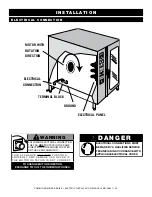
Electrical Connection(Bottom)
54-1/8" (1375mm)
7-9/16" (192mm)
33-7/8" (859mm)
41-3/8" (1050mm)
Treated Water
Intake (Bottom)
Untreated Water Intake
(Bottom)
WATER
DRAIN
3-5/8" (92mm)
2-1/16" (52mm)
21-11/16"
(550mm)
6-3/8" (161mm)
dimensions:
h x w x d
EXtEriOr
:
41-3/8" x 35-7/8" x 35-11/16" (1050mm x 910mm x 905mm)
EXtEriOr
witH
rEcEssEd
dOOr
:
41-3/8" x 39-7/8" x 35-11/16" (1050mm x 1012mm x 905mm)
interior
:
27" x 13-1/4" x 26-1/4" (685mm x 387mm x 665mm)
*
additiONal
wirE
sHElvEs
rEquirEd
FOr
MaXiMuM
caPacity
installation requirements
oven must be installed level.
hood installation is required.
Water supply shut-off valve and back-flow
preventer.
10•10
es
iN
capacity
Full-siZe pans: 20" x 12" x 2-1/2"
Ten (10)
eight (8)
gn 1/1: 530 x 325 x 65mm
Ten (10)
eight (8)
halF-siZe sheeT pans:* 18" x 13" x 1"
Ten (10)
nine (9)
on
wire
shelves
only
120 lb (54 kg)
MaXiMuM
vOluME
MaXiMuM
: 75 quarts (95 liters)
weight
net
385 lb
(175 kg)
ship
495 lb
(225 kg)
cratE
diMENsiONs
:
(
l
X
w
X
H
)
53"
X
45"
X
49"
(1346 x 1143 x 1245mm)
electrical
(
d e d i c a t e d
c i r c u i t
r e q u i r e d
)
10•10
e s
in
10•10
e s
in/sk
vOltagE
PHasE
cyclE
/
Hz
awg
aMPs
kW
amps
kW
at 208
1*
60
2 wire plus ground
67.0
13.9
69.2
14.4
at 240
awg 3
77.0
18.4
79.0
18.9
at 208
3
60
3 wire plus ground
38.6/ph 13.9 40.0/ph 14.4
at 240
awg 6
44.3/ph 18.4 45.5/ph 18.9
at 380
3
50
4 wire plus ground
21.1/ph 13.9 22.0/ph 14.4
at 415
awg 10
25.6/ph 18.4 26.3/ph 18.9
*
ElEctrical
sErvicE
cHargE
aPPliEs
208-240
208-240
380-415
water requirements
water quality minimum standards
TWO (2) COLD WATER INLETS - DRINKING QUALITY
ONE (1) TREATED WATER INLET: 3/4" npT*
ONE (1) UNTREATED WATER INLET: 3/4" npT*
LINE PRESSURE: 30 to 90 psi 2.8 to 6.2 bar
WATER DRAIN: 1-1/2" connecTion wiTh a 2" MiniMuM air
gap insTalled as close To The oVen as possiBle
using a waTer supply noT MeeTing alTo-shaaM’s MiniMuM
waTer QualiTy sTandards will Void This warranTy.
it is the responsibility of the purchaser to ensure that incoming water supply is
compliant with the specifi cations listed through adequate treatment measures.
installation of the combiguard
TM
water Filtration system is recommended, but
this system may not address all water quality issues present.
clearance requirements
Contaminant
Free chlorine
hardness
chloride
ph
alkalinity
silica
Total dissolved solids (tds)
Inlet Water Requirements (
untreated water
)
less than 0.1 ppm (mg/l)
less than 3 gpg (52 ppm)
less than 30 ppm (mg/l)
7.0 to 8.5
less than 50 ppm (mg/l)
less than 12 ppm (mg/l)
less than 60 ppm
LEFT 6" (152mm)
RECOMMENDED SERVICE ACCESS: 18" (457mm)
20" (508mm)
FROM HEAT PRODUCING EQUIPMENT
RIGHT 4" (102mm) TOP: 20" (508mm)
For air MoVeMenT
BACK 4" (102mm) BOTTOM: 5-1/8" (130mm)
For legs
counTer-Top insTallaTions MusT MainTain
4" (102mm)
MiniMuM
clearance FroM counTer surFace
* can manifold off of
one 3/4" line.

