YZ810
YZ810
YZ810
YZ810----106
106
106
106
User’s Guide
400-0543-001
6
7. Operation
7.1 VGA Wall Plate with Local Output (YZ810-106)
7.1.1 Wall Plate Connections
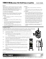
The VGA output from the PC connects to the VGA connector labeled
"COMPUTER IN" on the wall plate using standard VGA-type cable. The
PC audio output connects to the 3.5 mm jack labeled "AUDIO IN" on the
wall plate.
The "LOCAL OUT" connector on the VGA wall plate can be used to direct
the video from the PC to a local monitor in addition to the main output to
the projector. The "LOCAL OUT" connection does not need to be
connected when not used.
7.1.2 Power/Signal Present LED
The VGA wall plate with local output receives its power from the
Showtime switcher, but only when the projector power is turned on at the
wall controller, see 7.2.1.
The Power LED is on and red when receiving power from the switcher.
The LED turns green when a properly formatted VGA source signal is
applied to the input.
7.1.3 Presentations using Local Output
•
Turn on the projector power at the wall-controller.
•
If the room PC is not permanently connected to the wall plate:
o
Disconnect the video cable from the PC's monitor
o
Connect the PC to the VGA wall plate "COMPUTER IN"
o
Connect the local monitor to the "LOCAL OUT" using
standard VGA type cable
o
Connect the audio from the PC to the "AUDIO IN"
•
Select the PC input on the wall-controller that corresponds to the
VGA wall plate input.
•
The PC input is displayed on the local monitor as well as the
projector for the duration of the presentation.
7.2 Wall Controller
7.2.1 Power Key
The controller does not respond to input selections until the power key is
illuminated. Power on is indicated when the power key in the lower right
corner is green. Turn power on by pressing and holding the power key for
2 seconds. (Press and hold again for 2 seconds to turn power off.)
When the power is turned on, the projector is turned on and the electric
screen (if available) is lowered into position. When the power is turned off,
the projector is turned off, the electric screen (if available) is raised, and
the audio output is muted.
NOTE:
The power must be on for the wall plate to receive power from
the switcher.
7.2.2 Input Selection Keys
The input keys are only available when the power key is on. Press any of
the 8 input keys to switch to its associated wall plate input device. The
controller responds by illuminating the key green indicating the input
selection. Only one input can be selected at a time, and if an unused input
is selected a blank screen is produced since no video is available.
7.2.3 Volume Control Knob
The audio control is a single turn knob from minimum to maximum.
Audio control is only active when the power key is on. There are 5 green
indicators above the knob to indicate the volume level.
Note that setting the audio control to minimum does not mean sound is
not present on the speakers. In order to completely turn off the sound, use
the mute key next to the power key.
7.2.4 Mute Key
Press the mute key once to completely disable the output to the speakers.
The mute key illuminates red and the 5 indicators turn off when mute is
active. Pressing the mute key again restores the original audio level to the
speakers, turns off the mute key, and turns on the green volume indicators.
When mute is active, if the volume knob is turned in either direction,
mute is canceled, the mute key turns off, and the green audio indicators
above the knob illuminate to indicate the new audio level.


